Wooden Rack Unit spacers 032815

Many times in life you will need to mount a device in a rack without the assistance of a friend.
Sometimes you will need to leave a 1RU space in between devices for thermal reasons.

Sometimes supporting the device while you install the rack screws can be a great challenge. I’ve been known to use my teeth, knees, toe, etc…

I’ve also used audio gear as a spacer before which works if you have a spare 1RU, 2RU, 3RU audio device handy but you run the risk of trapping the device in the rack.

For those of you who may not know what a “rack unit” is, here is a wiki article that explains it.

WIKI article – Rack unit

So 1RU = 1.75″ (inches) tall and 19″ +/- wide

For reference, this is one of my Glyph hard drives measured with a digital caliper. 1 & 23/64 inches. Obviously if a RU is 1.75 inches the gear itself cannot also be 1.75″ or the tolerances for both the rack and the gear would need to be absolutely perfect. So manufacturers undersize their gear just a bit to make sure it fits. Rack manufacturers also build a bit larger than 19″ wide. I’ve had racks that were almost 19.25 inches. In this case the gear I own wouldn’t line up with the rack holes. Most of the racks I’ve measured are 19 1/16″ or 19 1/8″ wide. Plenty to fit a 19″ wide device.

IMG_1299

What might make a good spacer that is inexpensive, readily available and easy to manange? A modern wooden 2″x4″ is roughly 1 & 1/2″ x 3 & 3/8″.

IMG_1300

What this means is that (2) 2″x4″ scraps make great 1RU spacers to support gear while you install the screws. If you make the 2″x4″ scraps long enough and have them stick out a bit, you can use them as a lever to adjust the height of the device you’re mounting.

IMG_1302

I now keep a pair of these wooden spacers in my kit for when I need to shuffle gear around in a rack. They are a bit on the short side so I might put some felt on both sides to make them closer to the 1.75 inches. This will also keep the gear above and below from being scratched by the wood.

To measure or not to measure 032715

Today I had the plan of visiting an outdoor stage and measuring and helping eq and delay a sound system for a fellow audio engineer.

Upon arrival I realized the band was already sound checking and at that point I really couldn’t do much but discuss the elements of the PA and how I would go about measuring it and “correcting” things. Interestingly the visiting FOH engineer had a measurement rig of some sort but the little bit of discussion I had with him and his responses suggest he is using his measurement rig as an RTA and nothing more.

False Alarm 1

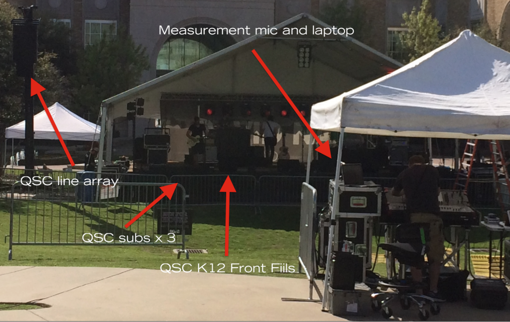
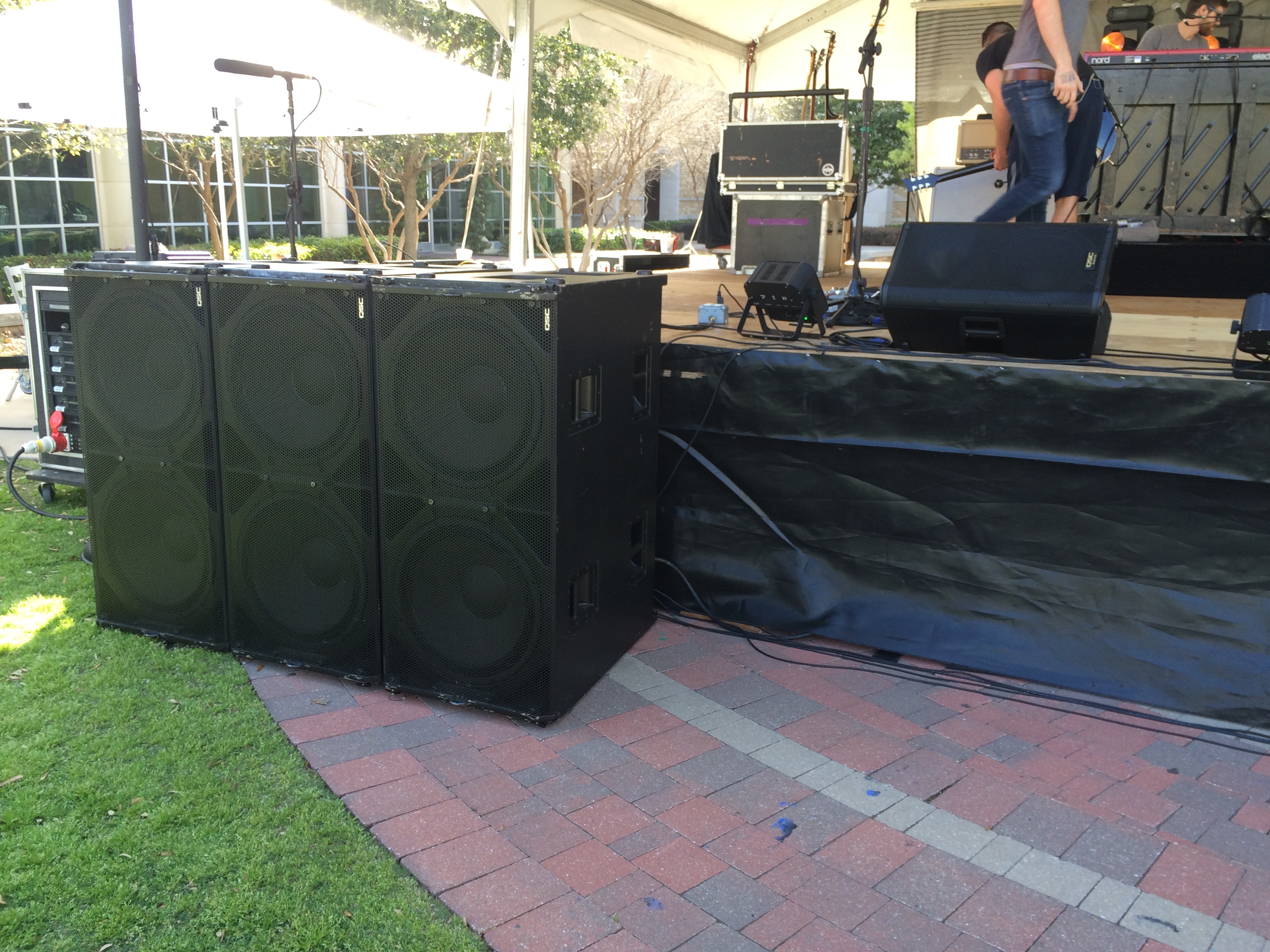
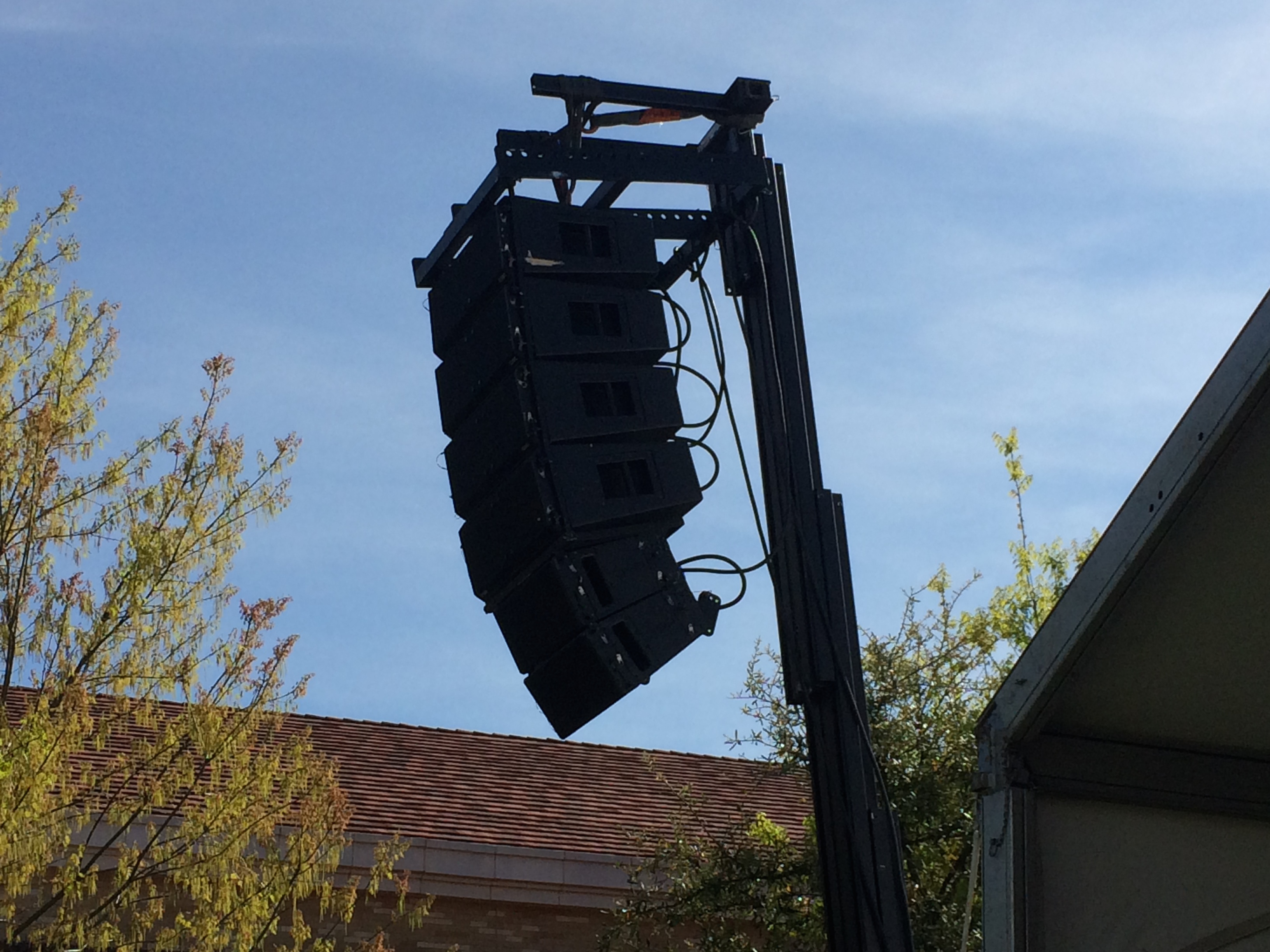
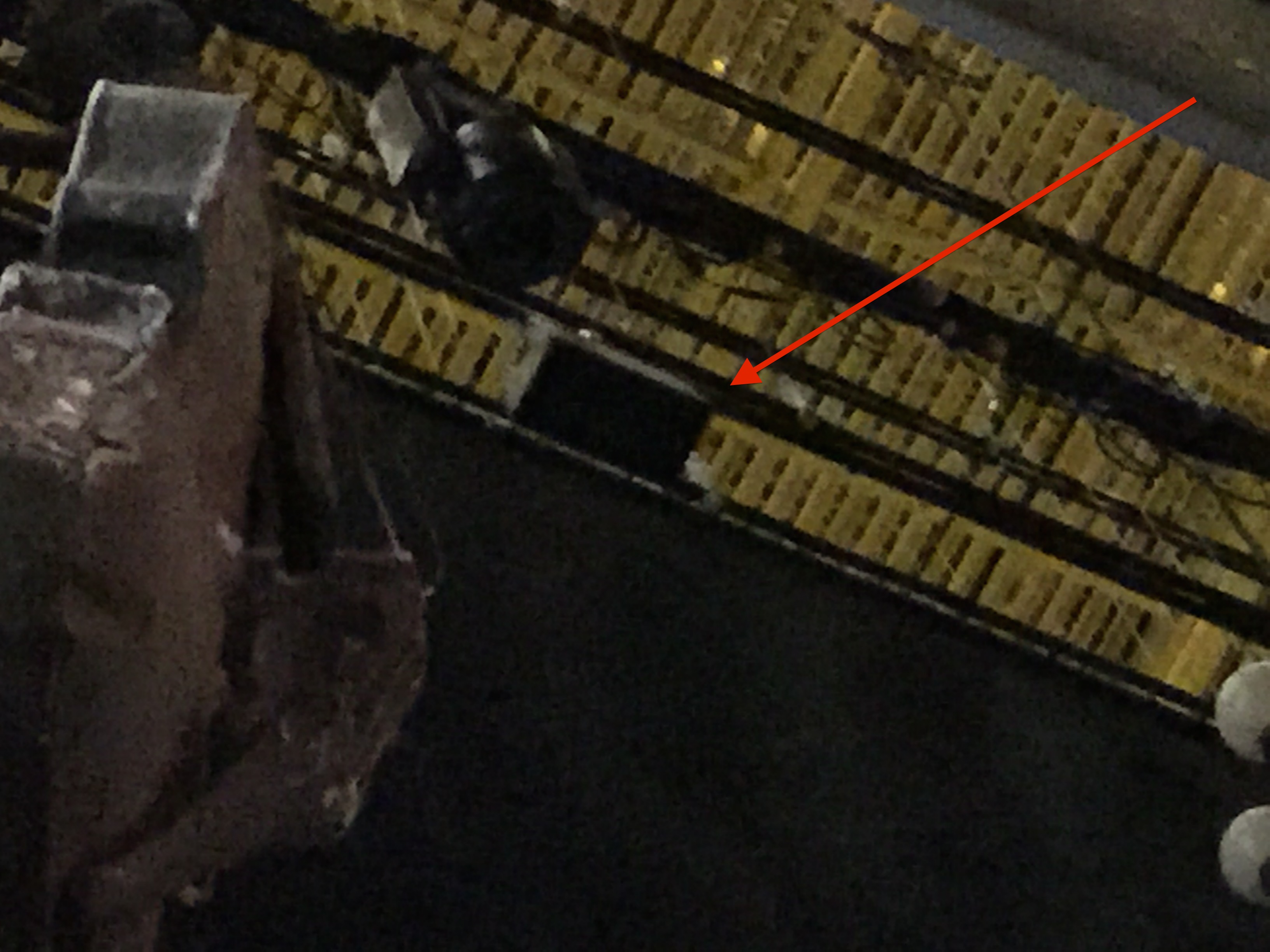
A few highlights. It’s not easily seen in the photo above but the front fills were aiming toward the tent roof instead of outward toward where the crowd would later be. When I asked about the front fills, the visiting FOH engineer said that he didn’t need them. How can you argue with that?

I had just left the position I was in standing as close to the stage as possible and at the very middle of the stage discussing with my fellow engineer friend how the Main L/R PA wasn’t covering the center well at all. I guess if you stand down front and you hear anything, it’s all good? There was certainly plenty of subs at that position.

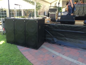
Speaking of subs, there were (6) double 18″ QSC subs split L & R.

QSC subs

The main speakers were hung from Genie towers.

QSC line array

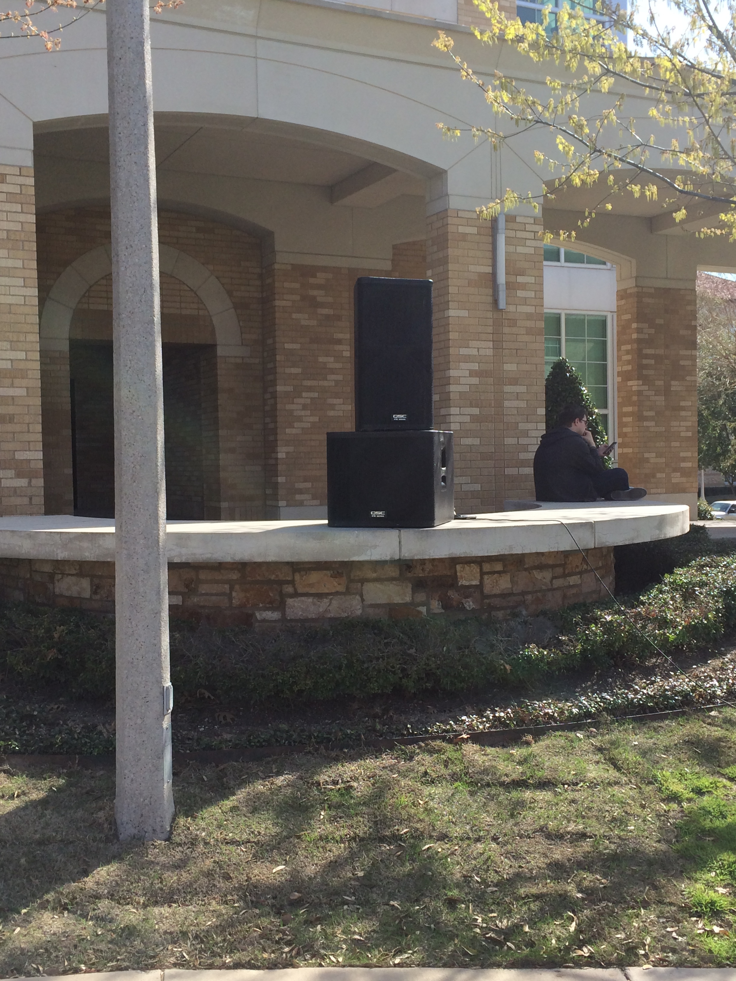
Then there was a pair of QSC KW181 subs with QSC KW152 mains on top of those acting as delays.

QSC delay stack

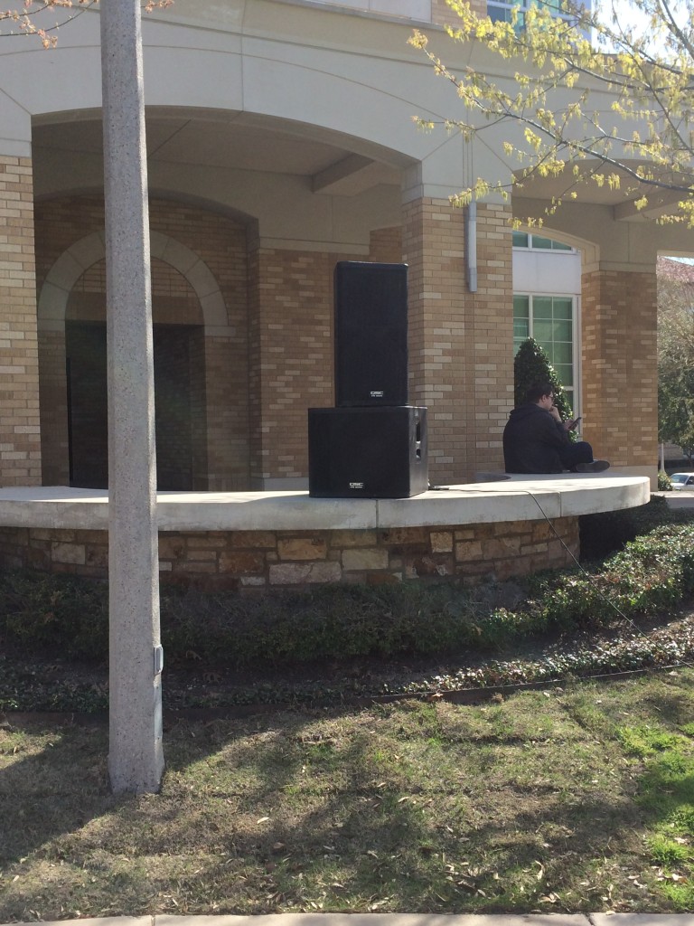
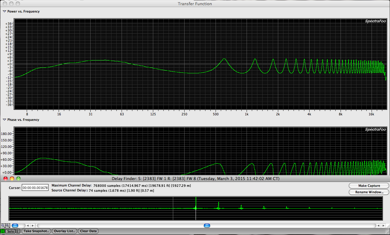
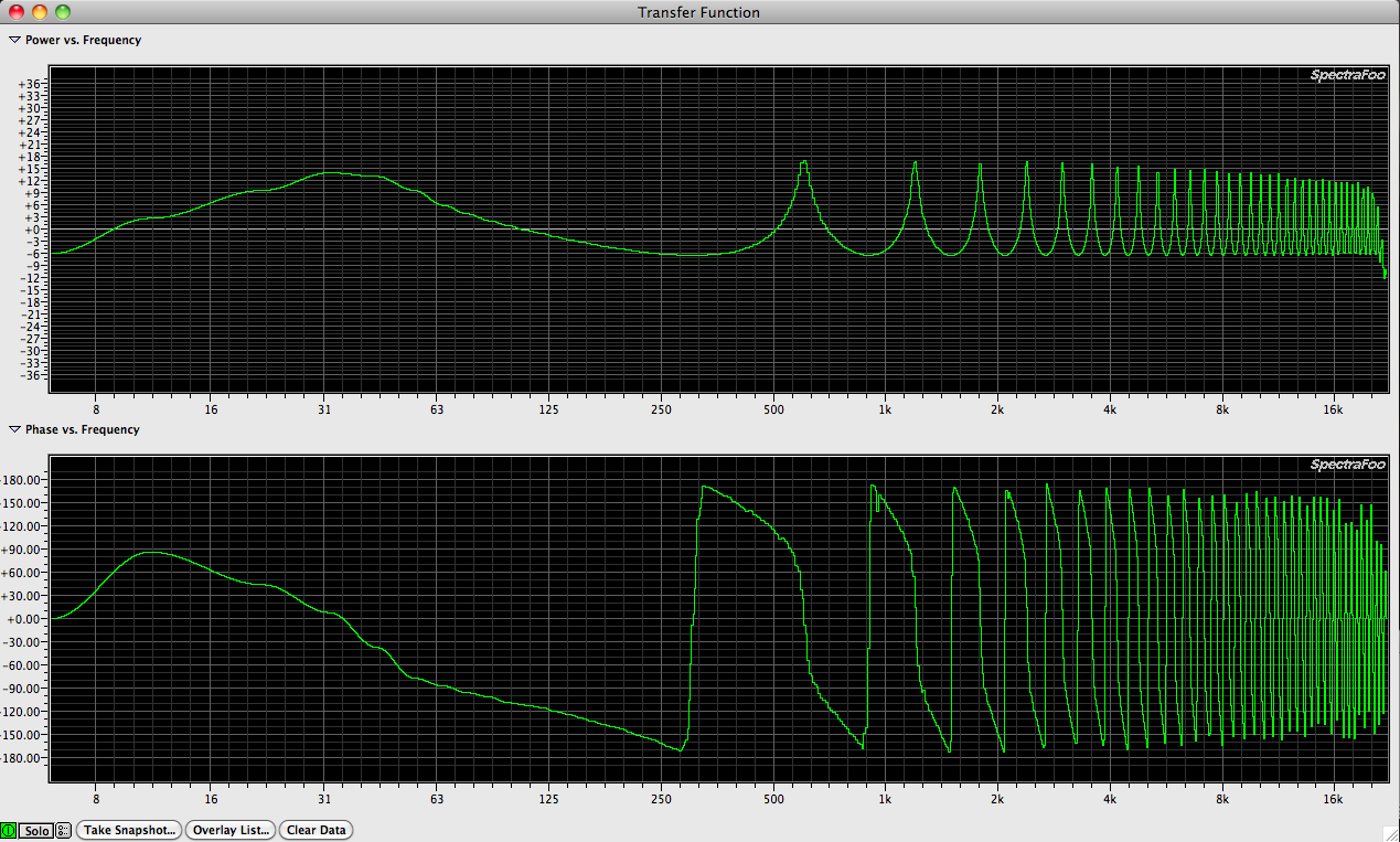
The delay speakers were at least 80+ feet away from the mains. I was told the visiting FOH engineer had 2.5ms on the delays and I heard him say he had the drummer play to set the delay time. I didn’t say anything but I thought…”Interesting”

In case this isn’t already clear, 1 foot of distance between speakers is going to dictate approximately 1ms of time delay.

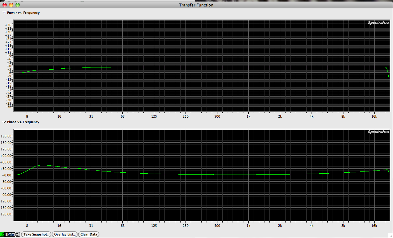
If you’ve got 100 feet of distance between speakers you’d be better of setting your delay time between those speakers (delaying the one further out in the crowd) 100ms instead of using your ears and a drummer. It isn’t a terrible method to use a click of some sort to time align delays with main speakers but when you’ve got a measurement app, there is zero reason to guess or not measure or just don’t delay at all. The visiting engineer may not understand how to make the measurement and set the delay time. Absolutely fine. I was in that position a few years ago. To be clear, setting delay times on speakers is one of the easier measurements to make and the easier settings to adjust. You can even verify your work. Once you insert the delay on your delay speakers, measure that zone again. If you’ve nailed the delay time, your mains and delays should measure the same with the mic in the right position and without moving it. Where do you put the mic? Where the two speaker zone (you’re only measuring one speaker at a time right?) cross over acoustically (not in frequency but in volume).

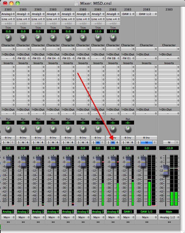
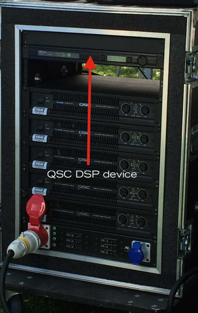
Since the subs were in front of the stage and the Main support lifts were to the side of the stage and back a big, logic would suggest that the subs would arrive early compared with the mains. This could be resolved with either the rack DSP or the FOH console (if subs were on an aux send) but obviously the subs were not aligned with the mains. Instead, the subs were early because when the kick drum hit, I could hear subs and then mains.

Basically, “I came, I listened, I learned, I left…” alll without ever taking my measurement rig out of my backpack.

A few things that became obvious while I was onsite.

1. Owning a measurement rig doesn’t mean you know what to do with one.

2. Front fills are necessary regardless of what the visiting engineer might think. It shouldn’t be left up to them to decide in my opinion. The system should be tuned and dialed in (levels between zones, eq and delay) prior to their arrival.

In this case the visitor engineer brought his own FOH console so it could be argued that being that far along in the system tuning process would of been impossible but I would counter with, “all of that stuff could of been achieved at the DSP in the rack” and should of been. Without a measurement rig and the skills it takes to use it and decipher the results you really are just hiding your head in the sand. I’m not saying it’s easy but I am suggesting it’s necessary.

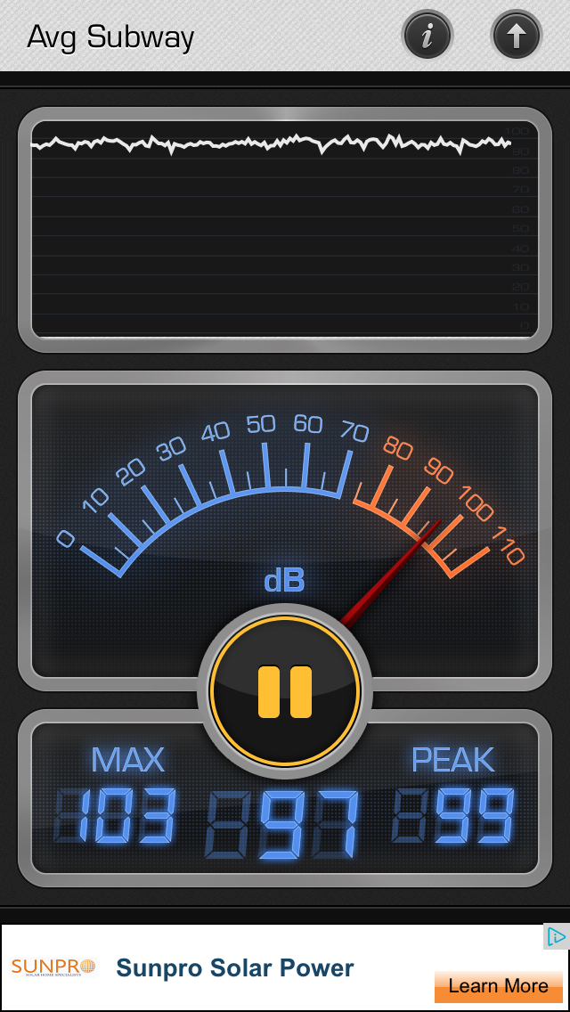
What I heard coming out of the PA sounded typical of what I expect of bands these days. Too loud, too much low end and lots of compression so nothing has any space. Like it’s all shoved into a bucket. I measured 100+ db on my Iphone at the FOH position and things were obvious louder as I got closer to the stage. I’m not sure things need to be that loud when you’re sound checking a band during the day and no one is around. Maybe I’m too old.

false alarm spl

QSC amp rack and DSP

In conclusion, a digico SD5 with a QSC line array with matching DSP and power amps can certainly sound better than what I heard. It’s clear after this experience that I still have a long way to go in my pursuit of system design and optimization but also in my people skills. If was difficult not to get involved in the whole conversation but no one asked me what I thought. Maybe next time I can arrive earlier and help the situation a bit. If the PA had been time aligned, zones balanced and the system tuned prior to the visiting engineers arrival, I don’t think he would of disliked the system. Instead he did the best he could with what he was given and what he knows. Clearly there is work to be done…

Smaart 7 fails to load and then asks for activation 032615

I just tried to start up Smaart 7 and the software wouldn’t load correctly. Then it said I wasn’t activated and I tried reactivation but that didn’t work either. Then I remember something I had addressed in a previous email between myself and Rational Acoustic’s tech support.

Here is the email exchange:

Imac Smaart activation email

Smaart 7 worked fine yesterday and I know it’s been registered and activated. What has changed on my rig to cause this issue? Based on John’s email explanation, the following came to mind.

Two things.

1. I have an older Imac hooked up to my newer Imac for transferring files.
2. I have an old HD from my MacBook Pro (also registered with Rational Acoustics) plugged into my newer Imac (registered with Rational Acoustics). Obviously those two harddrives are confusing Smaart 7 because as soon as I ejected them, Smaart 7 works again.

Smaart or SpectraFoo Complete?

Now that I own both SpectraFoo Complete and Smaart 7 and have used them both enough to have an opinion, which one would I choose if I could only have one? If it was for measuring sound systems, I would go with Smaart because of the Live IR function, delay tracker and the ability to have multiple overlapping transfer function traces active at the same time. These three things are a game changer in my opinion.

Rational Acoustics – Smaart 7 webpage

This isn’t say that SpectraFoo Complete can’t get the job done. In fact I tend to use SFC for most transfer functions just because I’ve spent more time with the app and know it so well.

Another thing I like about Smaart 7 is that I can capture the FR, PR, Coherence and IR at the same time. For someone like me who wants to share my results, this is ideal. Otherwise I’m left to take lots of screenshots which are hard to manage and impossible to revisit.

Why must one choose between cake and ice cream? I believe that the strengths of both apps used for the right purpose justify the cost of both applications. Metric Halo has lowered the retail price for SpectraFoo & SpectraFoo Complete enough to where I think anyone who works with audio would benefit from having it.

SpectraFoo Complete has instruments designed specifically for studio use (bit scope, bit range meter, phase torch, phase scope, power balance meter, vast level metering options (multitrack audio and Bob Katz K metering), THD analyzer, etc… as well as instruments for live audio purposes. Very useful.

SpectraFoo Complete instruments

Metric Halo – SpectraFoo / SpectraFoo Complete webpage

Line Arrays

One would think that with a market saturated with line array offerings, the old single speaker cabinet would be a dead horse but this is not the case. Just as a hammer isn’t worthless just because a wrench is needed. We need quality tools to reproduce our electrical signals and one shouldn’t make the decision on which tool to use without understanding how to select the best tool for a given purpose.

Here is some reading material to get you started. I’ll revisit this page soon…

WIKI article – Line Array

prosoundtraining.com – Line Array Limitations

Meyer Sound – Line Arrays: Theory, Fact and Myth

ProSoundWeb – Everything You Wanted To Know About Line Arrays (And Then Some)

Soundmansbible.com – Line Arrays vs. Point Source

Sound On Sound – Line Arrays Explained

JBLPro – Analysis of Loudspeaker Line Arrays

Countryman E6 032015

Today I’m guiding assisting a local church in securing some replacement cables and protective caps for their Countryman E6 & E6i mic elements. I previous designed and installed the PA systems in their building.

Most miniature condensor mics have some sort of cap. In this case the protective caps not only keep debris out of the element but also offer different frequency responses depending on which one you use. When looking at the images below note that the flat cap is the shortest and the most extreme HF boost is the longest cap. Considering that the cap slides onto the element housing and we have a glimpse of how very small changes near a mic can have dramatic results. Who would think that the amount of cap housing behind the mic tip would have this effect?

Miniature omni mics (if capped with a flat frequency cap) could easily be used for audio measurements. Some industry standard miniature omni mics include the DPA 4061 (which also has various cap options that affect the frequency response), Sennheiser MKE2 Gold and the Countryman B3 & B6 (both offering caps that affect the frequency response). You wouldn’t want use these mics via a wireless beltpack but if you have a way to get the mic signal wired up, no reason you couldn’t use them for audio measurements. Especially if you can compare them with a known measurement mic.

Countryman E6 protective cap – webpage

E6 user guide PDF

Here is some relevant information taken from the PDF manual.

Countryman E6 manual page 15

Countryman E6 manual page 16

Countryman E6 manual page 13

Countryman E6 manual page 12

Albert Einstein’s office

I got an email from a friend today that included this photo of Albert Einstein’s office when he passed away.
Alberts office

Here is a quote from the man himself that ties in well.

“If a cluttered desk is a sign of a cluttered mind, then what are we to think of an empty desk?”

– Albert Einstein

I think there is a legitimate justification for clutter and chaos. An empty room will sound different than a room full of furniture. Arguably better. Especially if the empty room is acoustically unflattering. I like neat and organized as much as the next person but neat and organized isn’t necessarily superior sonically. With our measurement rigs, this sort of thing is scientifically provable. How? Setup your measurement rig and send some pink noise into the room. Save a trace of the impulse / frequency / phase response. Now clear out the room and remeasure. Compare the results. I would venture to guess that the impulse response will now be much worse (lots of secondary reflections) and the frequency and phase response will have changed noticeably.

Even without a measurement rig, our ears are well equipped to detect ugly reflections. Simple. Clap your hands together in the space and turn around as you clap. Your ears will be provided with a sonic imprint of the acoustic space. The clap is exciting the space in the most important frequency range (the mid range) and you can hear what happens when you load the room with sound. This approach is no substitute for actual measurements but it is a good start. The first thing I do when I arrive in a new venue is clap my hands as I walk around to get an idea of what I’ve come up against. Standing on stage and clapping out into the house is a good test. Standing at FOH and clapping is another good test.

In the case of my office, I tend to let things back up and pile up. I am in the process of organizing right now so before I start the cleansing process I will take some before and after measurements. In the meantime, here are some pictures of what I have done to create some acoustic chaos in the room without just deadening it.

chaos 1

chaos 2

chaos 3

Prior to the added chaos and clutter, my office had an ugly & very short reverb tail. With the added white ceiling and wall treatment, it’s relatively free of reflections now. Things I record in my office are very neutral. In case you’re wondering what all those white things are on the ceiling and walls, it is packing material from a Meyer Sound speaker installation. The squares with round holes in the middle are packing material from some non Meyer speakers. I paid $0 for this acoustic treatment and I would argue that it is superior to a lot of what is available professionally because:

A. It’s completely random
B. It was completely free
C. I kept the materials out of the landfill

Sometimes chaos is a good thing. The desk you see in one of the photos is behind my mix position. There is no doubt that there is little if any reflections off that surface:)

Genelec speakers for measurement mic comparison 031915

I just received the second Audix TR40 measurement mic (discontinued) I have purchased on eBay. I was anxious to compare it with the other Audix TR40 I just received to see if they are close enough in frequency and phase response to use as a ONAX / OFFAX pair. Sometimes I don’t want to put up my matched pair of Earthworks omni’s I use to record and I was curious how well the Audix TR40 would compare to an Earthworks mic.

For my last mic comparison I used a Bose Wave Radio/CD device but this time I wanted something with a little bit more low end reach and also with a known response. I used my Genelec HT205 / 1029A pair in the studio for the sound source.

Here is the specs for the speaker:

Genelec 1029a HT205 spec

Here is the PDF manual for the 1029a which is the pro version with a TRS and XLR connector. The HT205 is the home theater version which has an RCA & XLR connector. Same device otherwise.

Genelec DS1029a

Here is the frequency response data from the manual:

Figure 7 shows the HF response at 0,15,30,45 degrees off axis. Note that the HF change is almost exclusively above 10khz.

Genelec 1029a figure 7

Figure 6 shows the on axis response based on the 4 dip switches on the back. With those dip switches you can reduce the bass response below 1khz and / or reduce the treble response above about 8khz.

Genelec 1029a figure 6

The speaker spec states 70hz to 18khz which doesn’t tell us much. Based on the frequency response chart, they could of easily claimed that it produces 70hz to 20khz. In order to know what is what, we need a +/- spec. For example, based on the frequency response given I would call this speaker 70hz to 20khz +/- 3db. A 6 db window between the highest and lowest frequency level within the provided response. Of special mention is a 3.3khz crossover point between the 5″ woofer and 3/4″ metal dome tweeter. We might expect there to be some phase shift at the cross over point when we measure the speaker. We might also expect to see a phase shift in the low end where the ported speaker cabinet begins to roll off mechanically roll.

Let’s take a look.

INSERT RESULTS.

EAW ANYA sound system 031915

EAW Anya dual column

EAW’s new Anya sound system may be the first entry into a new generation of PA systems. Let’s take a look.

EAW ANYA webpage

Here is an overview taken directly from the website:

EAW Anya is a complete, self-contained, high-power sound reinforcement system that adapts all performance parameters electronically, allowing it to be used in virtually any application. Columns of Anya modules hang straight, without any vertical splay, and Resolution 2 software adapts total system performance to produce asymmetrical output that delivers coherent, full-frequency range response across the entire coverage area as defined by the user. It is extremely powerful and immensely scalable, making it suitable for anything from small venues to the largest stadiums.

Each Anya module includes 14x 1-in exit / 35mm voice coil HF compression drivers loaded on a proprietary HF horn that expands to fill nearly the entire face of the enclosure. 6x 5-in MF cone transducers, arranged in two columns of three, use Radial Phase Plugs™ and Concentric Summation Array™ technology to enter the horn and sum coherently with the HF wavefront. Dual 15-in LF cone transducers use Off-Center Aperture loading to increase the spacing of the apparent acoustical centers, extending effective horizontal pattern control well into the LF range.

The module’s horizontal symmetry ensures coherent summation without anomalies through the crossover regions that result from physically-offset acoustic sources. This provides consistent, HF dispersion and broadband pattern control in the horizontal plane. Each Anya module includes a field-replaceable power and processing unit with 22 channels of digital signal processing and amplification to drive each of the module’s 22 transducers.

Via Resolution 2 software, Adaptive Performance controls all performance parameters of the total array to develop an asymmetrical output profile shaped so that all listening locations as defined by the user receive nearly identical response. By carefully crafting the size and spacing of the transducers, EAW engineers enabled Anya to create radical coverage patterns (i.e., narrowly focused and directed almost straight down) while maintaining an appealing, musical sound quality.

Here are some information related to the ANYA system:

Sound Image To Provide EAW ANYA for Tom Petty Tour
YOUTUBE – Robert Scovill discusses EAW’s Anya system with Tom Petty
Here is an interview with Dave Rat and soundgirls.org where they discuss the Anya system.
Anya system review by Dave Rat

Mic comparison 031515

With FFT sofware / hardware you can measure a microphone’s frequency and phase response easily. How? You need a speaker that can reproduce full range audio (doesn’t have to be flat or necessarily good although that is a good thing in general). Send pink noise through the amp / speaker / self powered speaker / etc…

Place you mic out in front of the speaker. 1 meter is a good distance since that is the distance speaker manufacturers typically use to explain how the speaker was measured by them.

1 meter = 3.28084 feet

Let’s call that 3 feet for this purpose. Probably doesn’t matter but why not try right!

Ideally you don’t want the speaker sitting on the floor (you’ll get extra low end but maybe that’s a good thing for your speaker) and you don’t want your speaker reflecting off nearby objects / walls / ceiling / etc… although even this isn’t a huge deal for this purpose.

Unless you start from an optimized situation acoustically, electronically, mechanically, etc… you’re not going to get an absolute result anyway. Instead you’ll get a response that relates to nothing. What good is this? Now substitute out microphone A with a mic that you know the frequency and phase response for (either one that came with a measurement file or at least a print out). In my case I have a good selection of Earthworks omni mics to use as a reference.

When you compare mics from different brands and models, you may have to make gain adjustments between each mic to maintain the trace upon the 0 db / 0 phase reference lines. Once you have matched basic gain between the first mic and the next, IF your unknown mic measures identical to your known mic, you’re golden. There are some variables to consider. If the mics are not in the exact same position, you will get slightly different measurement results. If the distance between the speaker and the mic changes (even slighting) it would be wise to recalculate the delay offset to make sure your phase trace is correct. If your known mic measures X and your unknown mic measures X, they’re matched and you can assume that the known mic has the same frequency and phase response as the known mic.

Take this a step further and you can test all of your mics periodically (using the same distance, same acoustic setup, same speaker / same settings, etc…) to see if you’re mics are functioning correctly. Unless you have some way to measure a very flat speaker in a very flat acoustic environment, don’t expect a flat response but if each time you test a microphone, it’s measurement result matches the previous one and so on, you at least know that the mic is still functioning. Obviously it would be wise to build a data library for each of your mics as they are purchased so you have a base line of what how that mic was performing when it was new. Mics get dropped, wacked, fall off stands, mic cables get tripped over. If you can test your mic selection and verify them against a measurement you made when they were new, that is great. How many old SM58s would test the same way decades later? How would an SM58 made this year test against one that was made 10 years ago? 20 years ago? 30 years ago? etc…

Ignoring the effect of age, moisture, internal windscreen deterioration, etc… I bet the sound of an SM58 has changed over it’s 50+ years of production. Do you know?

I only own a few SM58s. Nothing really old and nothing really new. Next time I have my rig set up I’ll test the ones I have and see how close they are to each other.

Here is another use for FFT software / hardware. You can compare mics that should measure the same to see if they do. Unless you are using mics that come with a custom frequency response print out like high end mics do (per serial number), the frequency and polar response shown in the literature is either a sample from one batch, an average of multiple mics or even worse, a mic that was hand picked because it measured the best. No way to truly know even if you ask. The trace we see in the Shure literature for the SM58 may be from the 60s. Do they update that frequency response and polar response each time they shift the manufacturing process? Do they measure sample mics from each batch? Do you know?

Quadcopters for audio purposes ???

I recently purchased an $80 SYMA X5C1 after seeing some of my fellow crewmembers playing with some quadcopters during the 2014 nutcracker run. I’ve always been fascinated with RC airplanes and helicopters but the quadcopter put me over the edge. I’m officially hooked! Way better than a video game. 3 dimensional flight.

What do quadcopters have to with audio? On the surface nothing really.

They’re a blast to fly around a theater before doors and after the show is over. A sort of toy to release the stresses of doing theater sound design. That is probably enough right there since I rarely “relax” in my role as resident sound designer for various arts organizations. Adding a quadcopter drawer to my workbox will be a good thing.

With regards to audio purposes, I can see how in the future I will be able to use the HD video camera function on a quadcopter to collect information about flow speakers and other things that are out of reach, etc…

I fly a small PA made up of QSC KW122 speakers for some of my ballet gigs and sometimes I’m not sure how the rear settings ended up if I’m not there to fly the speakers myself. Last time I brought them back down to check. Next time I’ll fly my drone up to take a look.

More expensive drones can broadcast real time video to the RC remote. In the future we will see drones mounted with 3D laser scanners that can map an entire venue and render out a CAD drawing. This will be handy for doing acoustic models of a space with prediction software like Meyer’s MAPP.

There are already drones that can fly preprogrammed paths. These sorts of aircraft make shooting scenes for movies and videos possible where a helicopter would not work.

There is a new quadcopter option coming out that not only follows the action but can link multiple quadcopters to the same target and follow them without any piloting. This is called “swarm”.

Plexidrone website

I’m sure the entertainment world will benefit greatly from having inexpensive drones. How about a drone with a wireless measurement mic mounted to it? Near field measurements of the drivers in a line array anyone? Who knows. Once you can program something to fly around in a certain way at a certain speed and follow a predefined path, there are all sorts of possibilities. Lead singer for a rock band being filmed from 4 different angles and broadcast live via the swarm function as they fly over the audience? It will happen…

Bose Wave Radio / CD 031515


I recently inherited a Bose Wave Radio / CD player.

Bose Wave Radio CD top

Since the device has an AUX IN, I can measure L & R speakers separately and their combined response. I’ve always heard good things about the Bose Wave System from people who own them. This will be an interesting experiment for several reasons. First of all, this will be by far the smallest stereo “PA” I’ve measured to date. Secondly, if the device sounds great and measures great, it will mean that I can use it as a reference for my studio mixes. If it measures well but sounds terrible or if it measures poorly but sounds great, that will be interesting to try to understand. Does the Wave System produce good sounding bass that is time aligned with the rest of the audio? Since the audio comes out the front but the bass is mecahnically ported out the back, maybe they are severely out of time.

Bose Wave Radio CD connections

WIKI – Bose Wave System

Bose Wave System related Google Patent page

Bose Wave Radio / CD official webpage

Owner’s Guide PDF

Quick Setup Guide PDF

Sadly the official owners guide provides almost zero information about the device itself. What is the frequency response? Phase response? What size are the drivers? Sensitivity?

Combing the 31 page user manual, the following screen shot is the only piece of information I found regarding the design of the device regarding it’s sound generating mechanics.

Bose Wave Radio CD design

Here is a cad drawing of the bass chamber:

Bose Wave Radio cad drawing top view

Here is a image from the Bose website showing how the rear of the two drivers creates ported low end that mixes together and comes out the rear of the device:

Bose Wave Radio CD bass chamber diagram

Stay tuned for the measurement results…

Sound System Design and Optimization with Bob McCarthy podcast


Today I stumbled onto a podcast with Bob McCarthy and Nathan Lively. Do yourself a huge favor and listen to it. Then think about what Bob has to say and listen to it again.
You can listen to the podcast here:

Sound System Design and Optimization with Bob McCarthy and Nathan Lively

This podcast primes the listener for understanding why Bob’s book is a MUST READ and worth whatever energy it takes to master the topics he provides. If you don’t already have it, go here and buy Bob’s book:

Sound Systems: Design and Optimization by Bob McCarthy

Location, Location, Location 031515

Whether you are designing a PA for a permanent installation or using the same PA day after day for temporary sound purposes, there is probably nothing more important than how and where you place your speakers. This includes the physical location of the speaker / speakers and how they are splayed and aimed.

In the real estate industry, the (3) most important factors to consider when purchasing a piece of property (with or without a building on it ) are LOCATION, LOCATION, LOCATION.

The same thing is true for speaker placement. One of the main reasons I put this website together was because I continually see audio engineers fail to follow the basic principles of speaker placement and speaker combining. There is a right way and a wrong way to do this and if you’re going to spend the money on the gear, you owe it to your audience and your clients to learn how to locate and manage your speakers. All of them.

When it comes to speaker placement, splaying and combining, Success is NOT an accident. There is no point in beginning the measurement and tuning process IF your speakers aren’t properly located and combined.

How do you know?

The shortest path to knowing is to read documents created by the fore fathers of this industry. Specifically, Bob McCarthy’s “Sound Systems – Design and Optimization”.

A spoiler alert. There is nothing simple about this matter. I’ve been studying sound system design and optimization for over 5 years and I still have a long way to go. Why do it at all? Because we don’t have a choice. If you use speakers, you are shorting your earning potential and your clients if you don’t know at least the basics about how speakers interact with a room and each other.

TDO stage monitors 031115

In previous posts I’ve explained that stage monitors should get the same attention given to the house PA. This post will provide further prove as to why.

It may seem unnecessary to tune stage monitors but they are speakers and obey the same laws of physics that speakers aimed at the audience must obey. Any full range speaker is a compromise between frequency response, phase response, bass extension, coverage pattern, cost, size, etc…

If there were such a thing as a “perfect speaker”, where would it measure perfectly? Pick an acoustic situation to optimize any speaker for and then change the acoustic situation. The frequency and phase response will also change to some degree (large or small). This is absolutely guaranteed. There are literally unlimited elements that can and will modify the frequency and phase response of a speaker or speaker combination. For example, boundaries such as the floor, ceiling, walls, corners where those boundaries meet, reflective surfaces, other speakers, etc…

Consequently, no matter where you place your speakers, you will need to make sure they are aimed correctly, splayed correctly and processed correctly, (using delay and complimentary (corrective) equalization if you want a relatively flat frequency response (which you do).

For the production this post is based upon, I came in to measure stage monitors prior to the final dress rehearsal for an opera production. This is actually the first time I’ve every measured stage monitors only. Traditional opera uses no amplification for the audience but does provide pit foldback (stage monitors) so the singers can hear the orchestra regardless of where they are on stage. The singers might be placed behind scenery and need to sing in time. They may be up on a set piece and too far away from the pit to hear the orchestra directly. On the roving carts is a TV as well that shows the conductor camera. Obviously whatever is being reproduced on stage is going to affect what the audience members nearest the stage hear if it’s not properly managed. Proper management of stage monitors includes how they are aimed and equalized.

With that all stated, let’s tune some stage monitors shall we. In this case the stage monitors are Renkus Heinz self powered cabinets. (model numbers to follow)

There are (4) roaming AV carts on stage that include a TV and a speaker with a 15″ woofer / horn. (3) of these roving carts are SR and (1) is SL.

tdo rover

There are also (4) smaller speakers flown overhead as split pairs. One pair is upstage, the other pair is downstage.

tdo overhead

(6) zones total. Each with it’s own level and eq control at the house Yamaha PM5D console (located backstage).

I set up my measurement rig and fed pink noise out of my Metric Halo 2882 into a spare channel on the PM5D console. I also fed another 2882 output right back into an input (creating a loop) to use as my reference signal. I plugged my Earthworks TC30K into input 1 of the Metric Halo 2882 and verified that P48 (phantom power) was turned on. Now I have a way of generating pink noise and sending it to all the speakers as well as a way to measure what comes out of the speakers and what comes out of my audio interface. I have a mic on a stand and with a long XLR cable to move it to the various positions on the stage. The physical loop out of my audio interface which is going right back in to my audio interface allows me to compare what is leaving my measurement rig with what is coming back from the microphone.

Using the Transfer Function instrument in SpectraFoo Complete, I configured my reference to be the loop and my source to be the measurement mic.

Here is a screen shot of the pre and post EQ for the rovers. Notice that in every case, there is excessive low end prior to tuning the zone (post EQ).


Rover#1.
Rover #1

Rover #2
Rover #2

Rover #3
Rover #3

Notice the frequency and phase traces for Rover #3. Pretty ugly. Signs of comb filtering. Certainly the worst of the 3 rovers. Rover 3 is near a black hard leg. This is the main difference between Rover 1, 2 and then 3. Rover 1 and 2 are in a relatively open area.

Regarding the last rover, we didn’t measure Rover #4 because it was a mirror of another Rover we did measure. We were also running out of time. We made a copy of the mirror rover’s eq setting and pasted it on that mix. It would of been better to verify things but you have to pick your battles.

Regarding the overhead speakers, a quick measurement of the upstage pair suggested that there was no need for EQ (given the time we had left). The downstage pair needed a slight EQ adjustment but I forgot to save a snapshot of that pre / post measurement before we stopped. Nex time. What I do have regarding the overhead speakers is a text book example of a horrible impulse response.

TDO WOH OH pair

Notice the indicated multiple arrivals. We would expect there to be (2) peaks if the mic wasn’t exactly centered between the two speakers being measured but the “mess” that is shown indicates that the speakers themselves are reflecting all over hard surfaces which is smearing the sound. Considering the set that was in place at the time which is essentially a bunch of hard walls wrapped around a raked stage in the middle, this is certain. If time allowed, we would ideally re aim those speakers to avoid reflections and improve the impulse response which is really a window into the quality of sound that you are measuring and presenting to the singers but this time, we settled for quick and dirty.

Speaker photos courtesy of Gregg Pearlman

pilot error rig malfunction 030315

If you ever feel really good about your measurement rig and your skills, volunteer to show someone how it works and how to test a piece of gear. For some strange reason, for me this always reveals how far I still have to go. When I work by myself I typically have good results.

So this is what happened most recently. I was doing a show and the house audio personnel asked me a question about their rig. I explained how I would go about trouble shooting what they described and said I was glad to help them. They brought me their Mackie mixer & their audio snake. I setup my SpectraFoo rig and configured it to test the mixer. When thought I was ready I sent pink noise to the mixer and back out of the main mono output. I got a very strange reading.

pilot error rig malfunction 4

To verify that my rig was working correctly I bypassed their mixer and looped out of my rig and back in again. Same behavior, different gain difference.

pilot error rig malfunction 5

Notice the delay finder impulse response:

pilor error rig malfunction delay finder 1

Like a skipping stone. I’ve seen this sort of behavior before (outside of the FFT instrument) when a signal is clipping. I also noticed some weird behaviors in the Mio Console itself. Trying to adjust the gain for the return channel was very touchy.

To make a long story short, it turned out that I was creating a feedback loop by NOT muting the return channel in the Mio Console.

Here is what I had. Notice that my return channel is feeding the MAIN buss. Perfect feedback loop.

pilot error rig malfunction mio 1 annotated

Once I muted the return channel like this:

pilot error rig malfunction mio 2 annotated

Everything was stable and this is the measurement I was able to get measuring the internal signal generator against the D/A A/D physical loop:

pilot error rig malfunction 8

This was a 15 minute detour and once again reminds me that the key to measuring is to build a rig, label everything and how you use it, build whatever configuration files you need in advance and test. Otherwise one routing mistake and your rig doesn’t work.

It turns out that the Mackie input to output was all good. We discovered some broken solder joints inside the snake box due to a failed strain relief. I tried to resolder things but the snake proved to be of such poor quality that the fix didn’t work.

Coherent – what is it and what does it tell us

There are a few instruments / windows & traces in a modern FFT tool.

These would include:

IR (impulse response). Typically in it’s own window. One of the first things you need to do when measuring a digital or acoustic signal is perform delay compensation so the two signals you are comparing are time aligned. If not, youre information will likely be faulty.

PHASE. The phase response is typically in it’s own window. It shows you the time different at each frequency between the two signals you are comparing.

AMPLITUDE (SIM3) / MAGNITUDE (SMAART) / POWER (SpectraFoo Complete) – These are all the same and relate to level.

If two signals are identical in time, phase & level, you get flat lines on your instruments.

Mansfield ISD PAC 030115

Another year has come and gone as I do another Texas Ballet Theater “Peter and the Wolf” performance at Mansfield ISD’s PAC.

Same JBL Vertec PA. The house audio engineers Bret & Daniel were a pleasure to work with again.

For a refresher, here is the first post I wrote about the venue.

Mansfield ISD PAC 021214

One of the things I have learned about measuring Line Array’s is that there is nothing magical about them. The overlap between each speaker in an array is ugly just like an array of speakers turned in the horizontal direction (like everything was done prior the rediscovery of line arrays in the 1990s).

So you have to choose where you place your measurement mic on a line array. If you walk forward and backward it’s fairly easy to hear where the HF (high frequencies) affect each other. I chose to put my mic on axis of one of the line array cabinets. The general rule is to make EQ decisions where it does the most good for the most people. I’m assuming that there are more people on axis of each line array speaker than in between them…

If you place your mic off axis of two speakers in an array you get a very different measurement than you do if you place the mic on axis of only one speaker. Next time I show this but I didn’t think to capture a trace with the mic in different positions (on / off) axis.

RF scanners and RF coordination software

Part of being a live audio engineer includes understanding and using RF (wireless) gear. In order to coordinate frequencies (make sure devices are tuned to compatible frequencies) and avoid interference from other sources like DTV and nearby RF gear, it’s vital to be able to see what the frequency spectrum is and find open frequencies. Otherwise you’re playing Russian roulette. There are many options when it comes to RF scanning. Some are handheld. Some are based around a computer.

This device is a stand alone unit that can be combined with a computer.

RF Explorer’s RACKPRO – rack mount RF scanner

Here is an alternative link to the same information:

RackPro

RackPro – demonstration video

Here is the PC software that comes with the RackPro unit.

Clear Waves – white space finder

Here is the Mac software that can be combined with RackPro.

RF Venue

Here is IAS (Intermodulation Analysis System) software by Professional Wireless

Professional Wireless IAS

Here are some handheld scanner options:

Various RF scanner hardware / analysis software links