My introduction to combining speakers properly came from reading Bob McCarthy’s book “Sound Systems – Design & Optimization” but it was during his SIM3 class when he demonstrated the approach that I clearly understood.
On paper the concept seems rather simple.
“-6dB + -6dB = 0dB”
Combine speakers at their -6dB point and they sum back to 0dB.
A key piece of information is that manufacturers state speaker coverage based on their -6db point. If a speaker has a stated coverage of 90 horizontal x 60 vertical, that means that traveling from 0 degrees on axis (ONAX) in an arc to being more and more off axis (OFFAX), when you get to 45 degrees in either direction horizontally or 30 degrees vertically, the mid / high frequencies will have dropped by 6db. If you need more horizontal or vertical coverage than that, you will need another speaker. The not so obvious question to ask is “at what frequency am I trying to combine them?” Speakers are not inherently linear in directionality. In general, speakers are omni directional at lower frequencies and more and more directional at higher frequencies so you have to consider which frequency you’re paying attention to. In order to clear up my own doubts, I recently wrote Bob to get his take on choosing the right frequency to combine speakers and this was his reply:
“6 db – the flat part of the beam width – typically 1k above but with small boxes could be higher. E.g UPA above 1k, UPJ 2k, junior 3k , UPM 4K”
I’ll add that speaker directionality is a moving target. Here is an example of what I am talking about. A directional plot for a QSC AD-S12.
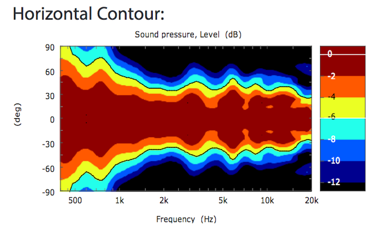
Pay attention to the red part which represents odB and where the yellow starts which represents -6dB. Between 2k and 15k, this speaker is rather consistent in directionality but it is by no means linear. At the two extremes, the cabinet is omni directional below 100 (not shown) and coverage begins to narrows above 8k. Where is -6db. I would take Bob’s suggestion and choose around 2k for this cabinet.
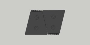
Let’s combine some generic speakers and see what happens. One of the mistakes we can make when assembling a sound system is to put two or more full range speakers side by side in a horizontal array and not to splay them at all. Like this (0 degrees):
The result of a 0 degree splay is broad band comb filtering, something to methodically avoid. You’d be better off unplugging one of them.
(INSERT TRACES TO ILLUSTRATE)
If you don’t already know what comb filtering is, please read this article:
soundonsound.com – What Exactly is Comb Filtering?
———————————————————————————————————————-
The opposite scenario would be to aim the speakers in opposite directions (180 degree splay) which would be silly. Like this:
Believer it or not, 180 degree splay between two cabinets would sound better than a 0 degree splay. In this case you would have no high frequency combing and extra in the low end. If it were me, I’d still unplug the one facing the wrong way.
———————————————————————————————————————-
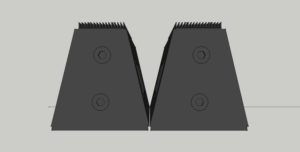
Options beside 0 and 180? Some might logically assume that a trapezoidal cabinet’s sides indicate the proper splay angle and simply butt them together like this:
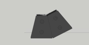
In some special cases the sides of a speaker cabinet do indicate the correct splay angle but in general the side angles of a trapezoidal box do not indicate the proper splay angle so it’s not an assumption we want to make.
———————————————————————————————————————-
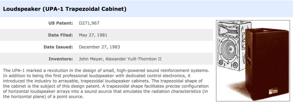
As a starting point for discussing proper splay, I chose the Meyer UPA as a point of reference because it was the first trapezoidal cabinet.
Here is an article that explains what made the UPA special:
mixonline.com – 1980 Meyer Sound Labs UPA 1 Arrayable Trapezoidal Speaker
QUOTE:
“From the outside, the UPA-1 was decidedly different: It was the first trapezoidal speaker (U.S. patent D271,967), now a common practice within the industry. Its sloped sides allowed the creation of tightly packed, wide-coverage horizontal arrays to minimize the comb-filtering effects that occur when spaced drivers reproduce the same frequencies.”
meyersound.com – patents
———————————————————————————————————————-
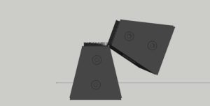
How does one splay Meyer UPA speakers for the right amount of overlap? Meyer Sound has done all the research for us and published the results. The proper splay angle for combining UPA-1P cabinets is 70 degrees. Like this:
On the other hand, the proper splay angle for combining two UPA-2P cabinets is 30 degrees which just happens to be the angle of the cabinet side. Like this:
The UPA-1P & UPA-2P share the same cabinet dimensions but use a different horn, have different coverage patterns and require different splay angles for proper combining.
The UPA-1P has a coverage patter of 100 degrees horizontal x 50 degrees vertical (-6dB).
meyersound.com – 2 UPA-1P spec sheet PDF
The UPA-2P has a coverage pattern of 50 degree horizontal x 50 degree vertical (-6dB).
meyersound.com – 2 UPA-2P spec sheet PDF
Because the sides of a UPA-2P indicate the proper splay angle, you can place them with their sides touching in what Meyer calls a “tight pack”.
meyersound.com – 2 UPA-2P tight pack
meyersound.com – 3 UPA-2P tight pack
With a UPA-1P, there has to be a gap at the front of the cabinets.
This PDF article explains how to properly combine a pair of UPA-1P.
meyersound.com – 2 UPA-1P 70 degree splay
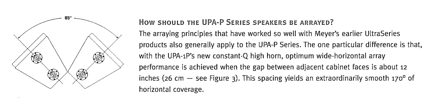
Seems simple enough but in the following PDF, Meyer states that the same cabinets can be splayed 85 degrees apart. What is the catch? You sacrifice a linear frequency response for more coverage. This suggests that while there is a correct splay angle for proper combining, there is some wiggle room.
meyersound.com – 2 UPA-1P 85 degree splay
In this Q&A PDF, Meyer provides the following details:
meyersound.com – UPA-1P Q&A
In the owners instructions for a UPA-1P, Meyer Sound has the following to say regarding designing arrays using UPA-1P cabinets :
meyersound.com – UPA-1P operating instructions
QUOTE:
“Array Design
Creating an effective array with the UPA-P requires a precise understanding of how to combine the coverage
area and SPL of the individual speaker with those of adjacent speakers. Array design is a trade-off between
increasing on-axis power and creating smooth transitions between the coverage areas of adjacent speakers.
As the splay angle (the angle between adjacent cabinet faces) decreases below the coverage angle of the indi-
vidual speaker, the power at the center of the array increases, but the coverage overlap between adjacent speakers
causes comb filtering and other frequency response variations. As the splay angle increases toward the coverage angle, the power at the center of the array decreases, but the variations in frequency response diminish. As the splay angle increases beyond the coverage angle, noticeable gaps begin to form in the array’s coverage area.”
———————————————————————————————————————-
Before we move on, it’s important to recognize that some cabinets have a rotatable horn. In those cases, obviously we need to verify the orientation of each horns in order to properly combine them and if necessary we may need to rotate them for our purposes (more vertical coverage or more horizontal coverage). A Meyer UPJunior has a rotatable 80 x 50 horn.
meyersound.com – UPJunior spec sheet PDF
meyersound.com – UPJunior operating instructions PDF
This is what Meyer has to say about splaying UPJunior’s properly for horizontal and vertical arrays:
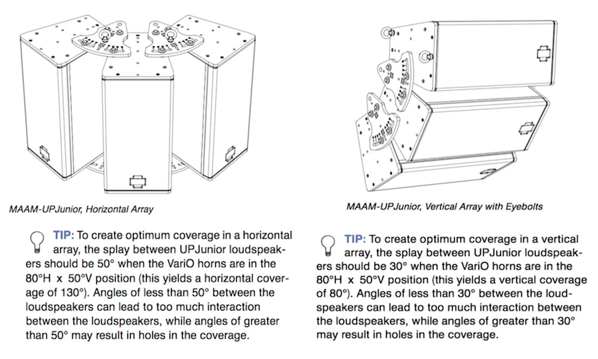
As you can see by now, Meyer Sound goes out of their way to make sure their users have the information they need to make good decisions. This is not true of most speaker manufacturers. In fact I can think of only one other company that might provide those details as part of their product literature. What this means is that for most speakers, you will have to figure it out for yourself. The first thing to do is to find the spec sheet for the speakers you will be combining so that you know what the stated horizontal and vertical coverage pattern is. From there you can either make your decision based on rules of thumb or use your measurement rig to find the proper splay angles.
For measurement demonstration, I have access to some QSC KW122 cabinets to illustrate the concept of splay & how proper splay affects your end result (seen via the measurement results). Note that unlike the Meyer UPA, the KW122 cabinet is not a trapezoid so the there is no method for achieving a “tight pack”. This means that the horns of KW122 array can only be so close together which limits your ability to combine them optimally:
qsc.com – KW series spec sheet PDF
A KW122 has a 75×75 degree horn. What QSC called Asymetric 75 degree. If you want to combine two KW122, a good starting point is 1/2 of the stated coverage pattern. In this case each KW122 is worth 75 degrees of coverage and combing two cabinets side by side would suggest a splay of 37.5 degrees apart.
INSERT 0 degree splay trace
INSERT 37.5 degree splay trace
INSERT 75 degree splay trace
What if the cabinets you have to work with don’t have a make and model shown (possibly home made) and your time is running out? This is where having a measurement rig is helpful. You would establish a base level and frequency response on axis (ONAX) of one of the speakers and then move the mic in an arc or better yet, leave the mic in place and rotate the speaker until you find the -6db point @ 2k. This experiment would indicate an approximate splay angle. If the -6db point was 25 degrees off axis @ 2k, you would need roughly 50 degrees of splay between the center of two of those speakers to combine them properly.
To illustrate the point that there is no “right” way to splay speakers but instead many opinions and many variables, you may enjoy reading the following thread on the prosoundweb.com forum
prosoundweb.com – Setting the proper splay angle
Note that some of the posts on that thread come from widely respected individuals in the industry. “It depends” could be the stated consensus. Distilling what I read, let’s go with this.
1. Ask the manufacturer for guidance. If anyone has a vested interest in making sure their speakers are used together properly it will be the manufacturer.
2. Use the stated coverage pattern of the cabinets as a starting point and adjust as necessary.
3. Measure.
If the manufacturer states how to properly combine their speakers, that is where I would start. I would verify that their stated method approximates the process previously described. If the manufacture doesn’t provide any information regarding combining their speakers (typical), I would ask them for guidance. If they can offer none, do the measurements and figure it out for yourself. Then share your findings publicly.
Ignorance is NOT bliss and with a measurement rig, you can stop being ignorant and stop relying on the opinions of others. Once you have learned for yourself the proper splay angle for a given speaker cabinet combination, you will be on your way to better sound and the confidence it takes to make good decisions about combining speakers in general.


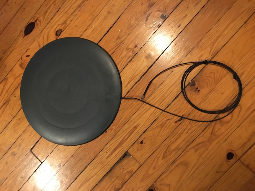
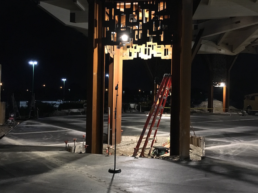 I just got back from a second trip out of state to help finish up a new sound system installation at a zoo. The sound system consists of multiple JBL CBT 100LA speakers. For aesthetic reasons, the speakers are mounted inside what the architect calls pods and are blocked by decorative metalwork. Another interesting decision is using the center of each pod as a drain for water that collects on each pod’s roof. These speakers are literally located inside the equivalent of a rain gutter.
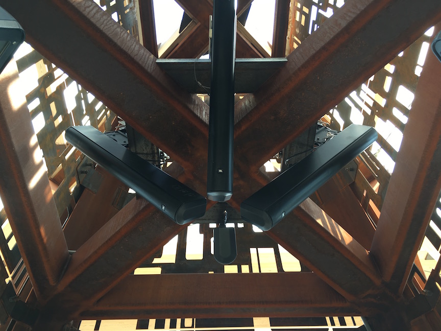
 Obviously there is a noticeable reduction in high frequencies when the speaker grills are filled with water. Without knowing this, I might mistakenly boost the missing high frequencies only to have too much once the grills dry out again. The moral of this story is that we should expect the HF response of our outdoor speakers to be affected by water if there are grills &/or foam involved. In this case, the intelligibility of human speech is mostly lost while the speaker grills are soaked. Solution? One option is to relocate the speakers outside of the pods. I doubt the architect is going to appreciate this suggestion. Another option may be to simply remove the grills which shouldn’t be a big deal. Yet another option may be to clear the water using some sort of audio tone or noise. I will be doing some experimentation to see how successful we might be in using pink noise or low frequency sweeps for “water abatement”. If it works, I’ll do another post with those details.


 Below are links to his facebook page, facebook videos, Youtube videos and his website where he shares his perspective on FFT Analyzers, Design, Testing and Calibration of sound reinforcement systems.
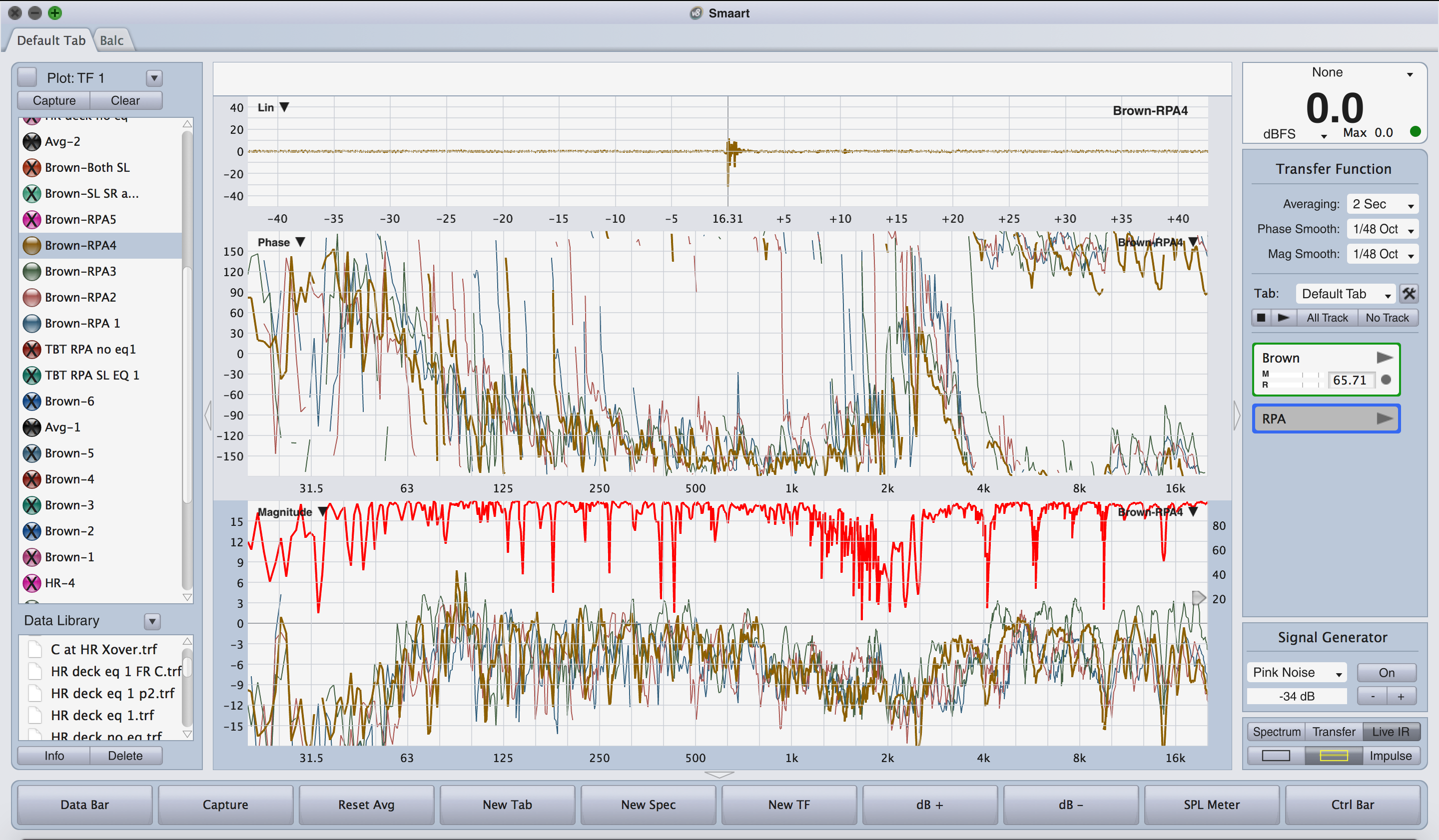
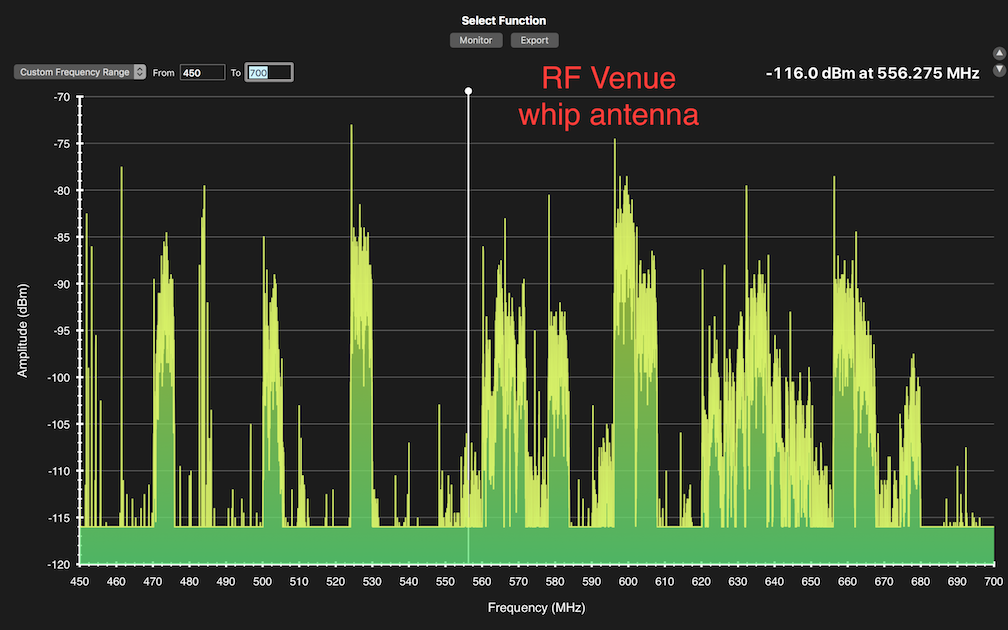
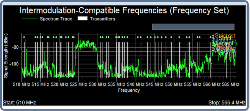
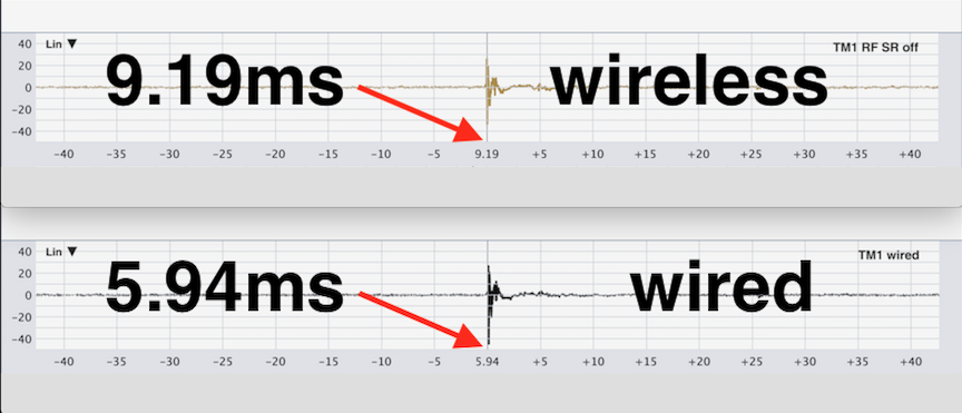
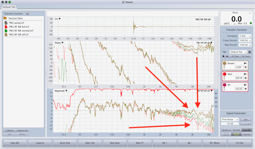
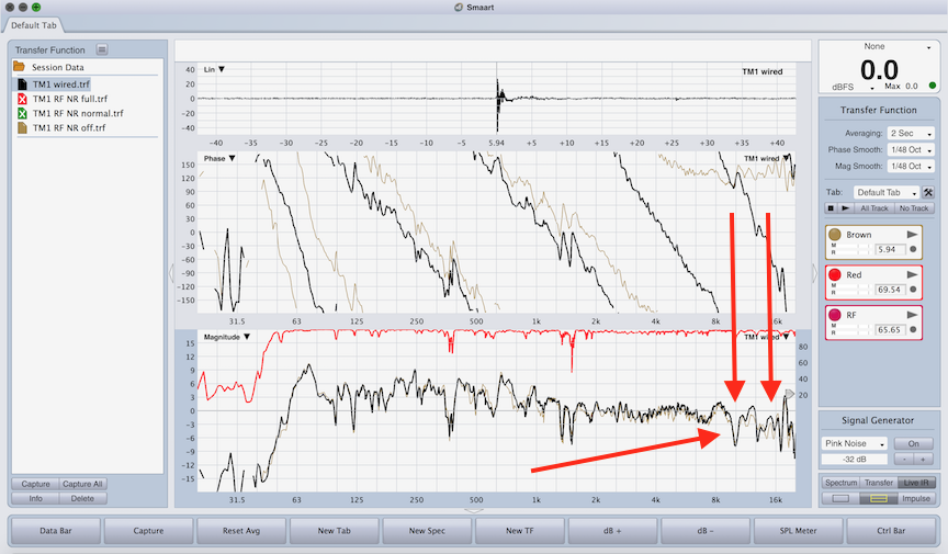
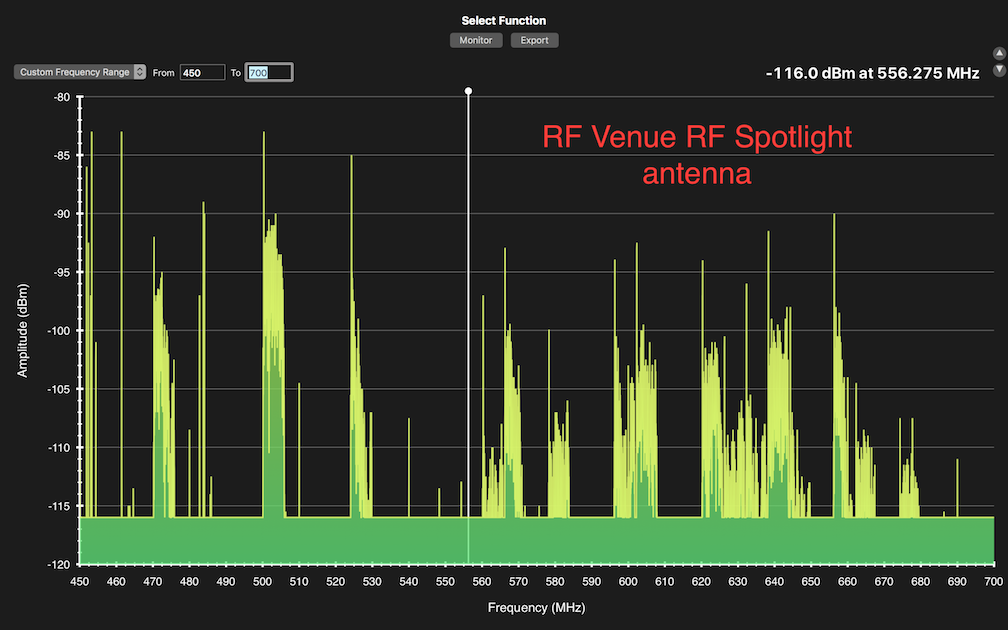 Tomorrow I will do a scan at the venue with their wireless mics on as a reference point and see what sort of reduction there is in hostile RF conditions. More soon…