Meyer Sound – MAPP XT

Meyer Sound has acoustic modeling software called MAPP and recently released a new version called MAPP XT.

MAPP XT

I spent more than an hour last night learning how it works. MAPP allows you to move speakers and mics around in a virtual venue and see what happens via the frequency response / impulse response and amplitude / SPL windows.

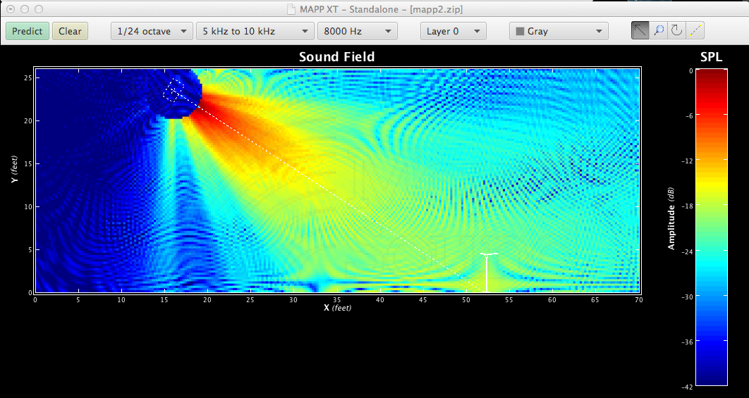
This model is of a single Meyer Sound – UPQ-2P in a medium sized room with one measurement mic. The model is showing what the response of that cabinet @ 10k. Pretty nice.

MAPP XT 10k no reflections

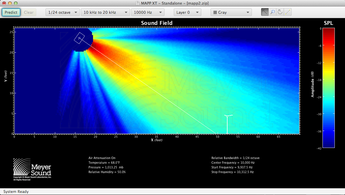
This is what you get when you enable the 4 boundary reflections. Not such a pretty design.

MAPP XT 10k reflections

One of the reasons MAPP XT can provide such useful information is because Meyer has done all the data gathering in advance. When you click on “PREDICT” in MAPP, it’s not calculating things locally on your computer. It’s actually calling into a server at Meyer Sound, doing the number crunching and then sending the results back to your screen. The true test of a model is whether or not what the model shows reflects what happens in the field. Does the install work as designed and modeled? How different is the final install compared to the model? My experience installing a lot of different Meyer PA systems in a lot of different venues (all modeled in MAPP) is that things are typically within a few degrees and a few percentage points of what the model showed regarding positions, angles and coverage. Amazing!

Meyer MAPP XT is free. They do require registration but that’s a simple process.

Here is a step by step instruction for getting up and running quickly:

MAPP XT tutorial

Once you have the software, you’ll want to watch the video tutorials to learn how to use it. Meyer’s video tutorial library for MAPP can be found here. Click on the Educational Videos link to access the videos:

MAPP XT resources

Scott Theater – design experiments part 1

In a previous post I explained how the existing house speakers were found to have issues and had to be temporarily replaced. Anytime you get to try something different in a space is a great opportunity to learn whether the new rig works better or worse than the previous rig. In this case the original rig consists of (2) Renkus Heinz TRC151/9 acting as a stereo L/R. These speakers have a 90 x 40 horn that can be rotated. The horns have been mounted with the slot in the vertical position up to this point but is that right horn orientation for the space? Is 90 degrees of horizontal coverage enough or too much? If we rotate the horn so that we have 40 degrees of horizontal coverage is 90 degrees of vertical coverage too much?

HL HR 90 degrees

The speakers used to temporarily replace the damaged TRC151/9 are QSC KW122 which have a 75×75 degree horn. Obviously if a 90×40 is the correct horn for two speaker coverage of the space in the horizontal plane, two 75×75 isn’t enough. If two 75×75 is adequate, 90×40 is too much in one plane and not enough in the other.

HL HR 75 degrees

To make matters more complicated, a while back a center speaker was added. A QSC KW122 to be specific. So previously the rig consisted of (2) 90×40 TRC151/9 and (1) KW122 in the center of those. Now the rig consists of (3) KW122s. When the change was made the decision was made to abandon the “stereo” concept because there is very little “stereo imaging” to be had in the space. The current configuration treats the space like a (3) zone mono PA. There are (3) sections of seats separated by (4) isles. Anytime you have the same sound source covering the same territory as another sound source, you’re creating comb filtering at the overlap zone. If you want “stereo”, you deal with this sonic hit but once you can make peace with the fact that for very few “stereo” isn’t stereo at all but instead a sonic mess, you can begin to design and configure without false notions as your guide. Currently the Scott Theater PA is mono and (3) zones. Fine. Not surprisingly the PA sounds better in this configuration. The FOH position is covered by only (1) of the (3) speakers (a first). There is minimal overlap and most of it is happening in the isles.

HL HC HR 45 degrees

Speaker Design and Testing – books

I have been refurbishing a pair of Renkus Heinz TRC151/9 speakers for a local venue and during the process have realized that in order to understand, design and optimize a sound system (made up of individual speakers), one must understand how a speaker works, why it is designed the way it is and how to understand what goes wrong and how to resolve it. One could assume that for an installation involving new speakers, they would all be functional but this would be a dangerous assumption. Certainly if you’re dealing with a system that is older, there may have been many opportunities for something to be done wrong. For example, something as simple as replacing a blown driver may lead to the replacement driver being reinstalled out of polarity. “Isn’t red the positive wire?” Maybe. “Isn’t the red terminal on a driver positive?” Maybe. Obviously we can’t leave it to chance that a system is properly configured. We must verify each part if we are to know that we are making things better and not just spinning our wheels.

How does one learn about speakers, speaker design, speaker testing?

Some books I have come across that seem worth having in your library are as follows:

Loudspeaker Design Cookbook 7th Edition – Vance Dickason
Testing Loudspeakers – Joseph D’Appolito

As I have been trying to verify that the TRC151 pair that I have are back to factory spec, I have realized that some times the measurement results for even a single cabinet as simple as a two way passive design can be overwhelming. What do you do when the measurement is cut and dry?

Ask questions. I’ve written Eminence to verify terminal polarity on the HF driver. I’ve written Renkus Heinz engineers to verify expected results.

I’m about to email McCauley Sound who provided the 15″ woofer for the Renkus Heinz TRC151/9 enclosure.

More soon.