(5) mic position measurement rig

After taking Bob McCarthy’s SIM 3 / System Design class it is apparent that moving one or two measurement mics around the room (as I have been doing) is an inferior method compared with using more mics and leaving them in place during the measurement / tuning process. Logical but who owns more than one or two measurement mics? I happen to own 10+ Earthworks omni mics. No excuse not to start using more mics!

Bob stated that (5) is a mimimum for combining (2) speakers. These are the (5) positions. I will use my recent measuring opportunity for reference.

Going from one side of the room to the other:
OFF AXIS – A
ON AXIS – A
XOVER – A/B
ON AXIS – B
OFF AXIS – B

Bob calls these mic position classifications:

OFFAX
ONAX
XOVR

There is one more mic position classification Bob calls SYM (for symmetrically opposite element) that I’ll ignore for the moment since this post is about (5) mics.

The ONAX positions are used for EQ decisions. The XOVR position is used for delay decisions and to verify that a proper spatial crossover.

Meyer Sound – SIM 2 User Manual PDF

I’ve been watching a Meyer Sound SIM 2 machine being auctioned on eBay.

Having recently taken Bob McCarthy’s class and asking a few questions, I know that SIM 2 uses a keyboard only (pre mouse) and so everything is done with key commands. Having grown up with DOS, this isn’t as scary to me as it might be to a younger person. Meyer Sound always provides a lot of good information in their user manuals and I couldn’t find a manual online for SIM 2 so I wrote Meyer to ask. Voila!

SIM 2201 User Manual

DATS – Loudspeaker Parameter Measurement system

In my quest to understand how speakers work, how various parameters are used to calculate building a speaker enclosure of a given size and shape, I am considering this software / hardware combination:

DATS Measurement and Accuracy PDF

True Audio – DATS

Parts Express – DATS

QUOTE:
Highly accurate measurement of loudspeaker impedance and parameters
Easy-to-use, fully-featured measurement software with intuitive interface
Compact USB measurement module with molded test leads and alligator clips
Software includes signal generator, scope, and measurement of inductors and capacitors

Data can be saved to create a driver parameter library or exported to popular box design programs
END QUOTE:

What do loudspeakers have to do with sound

The more I learned about Sound Systems : Design and Optimization, the more I realize that until I understand how speakers are designed, how crossovers frequencies are chosen, how boxes are ported, etc… I can’t possibly grasp what my measurement rig is showing me. One of the things that is clear when you’re taking Bob McCarthy’s class is that Meyer speakers are well designed boxes. I see (1) Meyer speaker out of 1000 other brands, most of which are passive, non self powered and no where near the quality of a Meyer speaker. Meyer speakers are nice but if you don’t know how to optimize and tune a lessor speaker, how well can the process go for you? Long before I will see a Meyer, I’ll see a Mackie or a Yamaha or a Renkus Heinz or a EAW or a QSC. While I would prefer to work exclusively with Meyer speakers, it’s not gonna happen any time soon. What I am left with are typically 2 way passive designs. My current mission is to learn about how to design, build and optimize a 2 way loudspeaker. Fortunately I have a sibling that is way ahead of me. True, owner of Toby Speakers.

tobyspeakers.com

The first pair of speakers are going to be based on a coax 8″. Why? Because I already have (2). I’ll pull the spectral crossover board off the back and extend the 4 wires to locate it on the back of the box. This way I can play with both a passive configuration and also an active configuration where I can use DSP (digital signal processing) to time align / phase align the two drivers and also flatten the frequency response. Next I’ll build a non coax pair with the same design concept. Once I understand what to expect out of a two way loudspeaker, I have a three way design I want to experiment with.

Radial Engineering “Gold Digger” – mic selector

One of the things that SIM 3 can do (using branches) is select the desired mic when you change to a different branch. For those of us who don’t have SIM 3 or if you do, don’t have the Meyer Sound mic selector, Radial Engineering’s Gold Digger mic selector may be a welcome addition to your rig.

Radial Engineering – Gold Digger

YOUTUBE – Gold Digger explained

Other than 48v phantom power and some relays there is no other circuitry. 4 mics in / 1 output. You can only select one of the 4 mics at a time so no concern of having more than one mic active. Since phantom power is provided, there is no loud explosive sounds coming from the mics when you switch. If you have Smaart 7, you can have more than one active live trace which is arguably better than having to view the results from one mic at a time but I can still see how being able to switch between mics may speed up the measurement process. If you have a 2 in / 2 out interface like the popular Sound Devices USB Pre 2, the Gold Digger mic switcher is a no brainer.

SIM 3 branches explained

I’m reading user guide for Meyer Sound’s SIM 3 and thought I would share…

Meyer Sound – SIM 3 UG PDF

On PDF page 57 “Chapter 3: SIM 3 Configurations and Branches”:

QUOTE:
3.1. SETTING UP BRANCHES 3.1.1. Overview
Within SIM 3, the setup and management of the signal paths from console through processor to the loudspeaker and room are organized into Branches. A branch consists of three measurement points:
■ Console: The Console is the audio input into the sound reinforcement system (source), typically the output of a mixing console or other source. This measurement point is exactly the same as the processor input.
■ Processor: The Processor is the audio output from the signal-processing chain that lies between the console output and the amplifier input. Typically this chain includes equalizers and delay lines.
■ Microphone: The Microphone is the output of a measurement microphone located at some position in the venue that captures the audio from the loudspeakers within the room.
Within a typical SIM measurement session, the user will create many branches to have complete information on all the elements of the sound system and the interaction between them at different locations.
3.1.2. Defining Branches
A branch is a series of three connected measurement points that monitor the flow of a signal from origin to its destination. The normal flow is from a console output through a processor to a speaker in the room. The three access points are Console — the point of origin, Processor — the output of the signal processing chain, and the Microphone.
The primary requirement is that all three points are driven by the same original source signal. With this satisfied, the measurement points can be used to make transfer function measurements that will characterize the processor electrical response and the acoustical response of the driven speaker in the room.

END QUOTE:

Here is a diagram showing the “three measurement points in SIM 3”

Meyer Sound SIM 3 - Branches diagram

SIM 3 & Galileo / Smaart 7 & DSP work around

One of the things that I have NOT been doing is taking measurements at the processor outputs. My typical measurement system is based on “CONSOLE / ROOM” as Meyer SIM 3 would label it. Without the “PROCESSOR” node, you have to guess how to shape your parametric EQ to match the room response. I know some system engineers who think that is fine but I’m having second thoughts. More information and less guess work saves time and time is something that is never unlimited.

SIM 3 lets you take measurements between CONSOLE, PROCESSOR & ROOM at the same time. If you’re using SIM 3 in tandem with a Meyer Sound Galileo or Galileo Callisto DSP unit, you have access to it’s input / output signals as well as muting using a single SIM BUS cable. SIM 3 relies on what are called “BRANCHES” to manage signal path routing and measurement points. Once the branches are setup correctly, you can move fast and efficiently between any 3 measurement points.

With Smaart 7, it’s possible to view an unlimited number of live traces (within the processing power of your computer). For example, one live trace could show CONSOLE TO ROOM response. Another trace could show the CONSOLE TO PROCESSOR response. Another trace could show the PROCESSOR to CONSOLE response, etc…
This functionality also allows for viewing the response of multiple measurement mics at multiple locations at the same time. Something SIM 3 cannot do. Within the limitations of your audio interface and the qty of mics you have, this opens up a lot of possibilities.

One of the measurement obstacles we are left to face with modern DSP is how to access the processor inputs / outputs. With analog processing, a Y cable is the solution. With DSP, the same Y cable may be used but there may also be a more efficient way of accessing the processor signals. For example, there may be a routing block that allows for selecting different signals routed to the same output. This is something I will be working on over the next few weeks. Having seen Bob McCarthy take great advantage of SIM 3’s overlapping CONSOLE / PROCESSOR / ROOM traces, I’m convinced. My days of guessing frequency, gain and Q settings to provide a complimentary EQ trace are over.

Consequently this evening I began assembling and cabling up a DSP rack based around an XLR patchbay and a recently purchased BSS London BLU 160. Once the rig is complete, using Smaart 7, I will be able to measure the (8) analog outputs of the DSP unit as well as the CONSOLE output and whatever measurement mics I’m using. Pictures of wiring explanation to follow.

SIM 3 / System Design with Bob McCarthy – post mortem 1

Now that the 4 day class has ended, I am left with my class notes and Sound Systems : Design and Optimization Second Edition to revisit the information Bob presented in class. One of the statements Bob made that seems vitally important is that he places the mics where he wants the speakers aimed. This is a much different concept than what I normally get to do which is tune the system AS IS. Where I put the mics where the speakers are already aimed. One means your speakers are aimed correctly when you’re done and the other (my current method) is a wild card left up to the previous installer / sound provider / etc…

Many times I have zero control over anything but system tuning via the console output EQ. Some times I am provided with zone control and have the option to adjust delay times between front fills and mains, underbalc delays and mains, etc…

The only time I have the opportunity to control the entire system is when I build it myself. This may be an install I’m working on or it may be a temporary system I’m providing for an event. Regardless, 75% of the sound systems I use are not mine to aim. I guess in that 75% section of my opportunities, tuning the system without the option of aiming it is all I can hope for.

What Bob provides in his book but explains in a way that I understand it better via his class is how to understand whether things are done correctly or not (regardless of whether I can do anything). If I can analyze a system and understand what is right and wrong while still having a successful audio event, that is a valuable experience.

Bob repeatedly states that the goal is to anticipate what you want to see when you measure something and be able to recognize (via a library of IF / THEN experiences) what is causing a different measurement result. In one case we fought trying to time align one speaker to another and the results kept on changing in the extreme HF range. Eventually Bob pointed out that the HVAC had recently came on and now we were seeing the results of a temperature change and air movement in the room. “A moving target” of sorts. Bob would adjust the time between the speakers for near perfect phase and then things would move the slightest amount. He would readjust the delay time and then it would change again. What to do in a case like this? Optimize as best you can and move on.

I am looking forward to trying what I witnessed Bob do in class on my own. I have a feeling Bob makes it look real easy. Hopefully between his book, my class notes and having watched him, I’ll be able to adopt the various protocols he follows to design and optimize a system. A system could be as simple as (2) speakers. Bob stated that once you understand how to combine (2) speakers correctly, a more complicated system is tackled using the exact same concepts and procedures.

I’m sure this post will continue to grow and divide so I’ll stop here and get back to reading Sound Systems : Design and Optimization again.

Bob McCarthy / SIM 3 and System Design – DAY 4

The last day of class was spent working on time aligning a sub to it’s main and time aligning a delay to it’s main. We also learned how some high end functions of the SIM 3 machine. For example, how to measure THD and how to do a “console check”. How to verify polarity. At the end of the day, we received a certificate of attendance and Bob signed books.

It’s always fun to be a participant in a class full of experienced audio engineers when it’s time to help pack up the class rig. I can’t think of a more copacetic group of professionals. Like ants in a colony…

If only audio gigs in general were that well staffed and organized

🙂

Bob McCarthy / SIM 3 and System Design – DAY 3

DAY 3

Current Temp: 67 degrees F
Humidity: 77%
Precipitation: 6%
Wind: 6 MPH
Pressure: 29.96 Hg
Dew Point: 61 F

I woke up earlier than I need to this morning. Lots of thoughts running around in my head about phase. Today we learned how to take a set of speakers and combine them correctly. Both as a unity pair and as a main / sidefill sort of configuration where the sidefill is covering a much shorter distance. The most important discovery for me was that a set of speakers may require a splay angle of X when coupled at unity but a different splay angle when coupled in a main / sidefill configuration. My assumption would be that the splay angle is fixed based on upon the cabinets used but this is simple wrong.

I’ll review my notes and add more soon.

Bob McCarthy / SIM 3 and System Design – DAY 2

Day 2

Current Temp: 99 degrees F
Humidity: 57%
Precipitation: 6%
Wind: 12.46 MPH / S
Pressure: 29.83 Hg
Dew Point: 61 F

There is so much important information coming in but a few highlights of Day 2,

We learned to decipher the SIM3 phase trace. With LF on the left and HF on the right, the general concept is that when you’re going down hill (breaking) you’re in the past. When you’re on the flat lands you’re in the present (coasting) and when you’re downshifting and applying throttle (climbing), you’re in the future. If you find a point on the trace where it goes vertical, you’ve experiences a rotation of phase. For example 180,360, etc…

For a phase corrected loudspeaker such as the Meyer ????, you may have only (1) vertical point which is near perfect for a 2 way loudspeaker.

INSERT TRACE

and how to find the -6 db contour of a speaker starting with ON AX NEAR, OFF AX NEAR, ON AX FAR, OFF AX FAR, and then working along a curve where you lose spl by traveling off axis but gain it by moving closer to the speaker.

If I can get some photos of the tape on the floor we used to graph out the contour, I’ll add it here. Same for one of the phase traces.

Today it finally cooled down a bit in the afternoon and then started to rain a bit in the evening.

Bob & Jason had dinner with Bill Eckenloft & his associate Declan and myself and discussed Broadway sound design.

Bob McCarthy / SIM 3 and System Design – DAY 1

DAY 1

Temp: 67 degrees
Humidity: 77%
Precipitation: 6%
Wind: 6 MPH
Pressure:
Dew Point:

Today is the first of 4 days with Bob “606”.

I’ll do my best to gather as much information as possible and report back each day.

The end of our Day 1 class morphed into a meeting between Harry Brill Jr’s Smaart 7 class and our group at a nearby tavern with a few guest SIM3 engineers attending (Dave Lawler & Craig Doubet). It was great to talk with people from the Smaart class and hear what they’re going over. If the classes hadn’t overlapped, I would of taken both classes…

Next time!

FYI, Harry Brill Jr. has some good reference stuff on his Tiger Audio website.

Rational Acoustics – Harry Brill Jr bio
Harry Brill Jr – Tiger Audio Inc

But enough about Smaart & socializing…

What did Bob talk about on Day 1?

1. Frequency / Time
2. Transmission speed
3. Transmission loss
4. Temp & Humidity
5. Frequency range
6. Wavelength
7. dB scale
8. Coverage angle
9. Coverage shape
10. Beamwidth
11. Summation amplitude
12. Summation phase
13. Coupled arrays
14. Uncoupled arrays

Even with lots of questions, we apparently made it through the desired information for day 1!!!

In case you’re wondering, pretty much everything Bob covered today is included in his book, “Sound Systems – Design & Optimization”
bobmccarthy.com – Sound Systems Design and Optimization book

We may have covered a few things that aren’t in the book due to questions but 99% of the information came out of the book. If you don’t have it, GET IT!

Stay tuned for DAY 2 post…

HS basketball gymnasium PA – part 2

After hunting for some rigging hardware (from a rigging supply) yesterday, this morning I met with the ISD crew about the game plan for rigging the new speakers. We used 1/8″ aircraft cable, 1/8″ thimbles & the end terminations were made with 1/8″ copper sleeves using a Nicopress 63V-XMP crimpe. Each tool & sleeve combination has different specifications. For example, a different crimping tool may need more or less crimps to hold the total weight. For 1/8″ sleeves, you use the oval P groove & the termination requires (3) crimps. Each of the 3 crimps should measure .353 inches wide with a digital caliper. We used 1/4″ Crosby screw pin shackles which are rated for .5T / 1000lbs @ a 5:1 minimum safety margin. What this means is that you could hang 5000lbs from the 1/4″ Crosby shackle before it would break. Rated for a SAFE WORKING LOAD of 1000lbs, means that this 100lb speaker is going to be safe in the air and stay put. Since we have (2) cables on each cabinet, either one could fail and the full weight of the cabinet would be easily supported.

These EAW AX3 series cabinets are very back heavy so using only the front support points they hang upward toward the ceiling. We used a 3rd rigging point on the cabinet with 1/4″ shackles and rated chain for the rear pullback point which allowed for setting the proper downward angle.

Trinity EAW AX3 before pull back point installed

Here is a photo with the (6) EAW AX3 cabinets flown and the old Peavey PA system uninstalled.

Trinity EAW AX3 installed

I mentioned in the first post covering this project that the existing PA was flown when it wasn’t designed for being hung. Here is a picture of one of the cabinets the ISD crew took down.

Trinity Peavey 215 with user added rigging points

measurement traces to follow…

HS basketball gymnasium PA – part 1

I fellow audio engineer invited me to go with him to figure out how to hang some better speakers in the gymnasium at his child’s school.

The current system has a few things wrong with it. It appears all the HF drivers are blown. The speakers are mostly aimed at the walls and ceiling and not at the seating areas. The existing speakers didn’t have rigging points to begin with so the ISD staff “customized” them and hung them anyway. In case you’re wondering, this is NOT acceptable. NEVER HANG A SPEAKER THAT IS NOT DESIGNED BY THE MANUFACTURER TO BE HUNG. You could kill someone.
Trinity Peavey 2

Trinity Peavey 1

Here are a few shots of the current 15 band EQ curve. Of special note is the 12db boost on the input gain followed by almost all boost on the EQ filters. Also note the LF cut fighting against the 25hz, 40hz & 63hz boosts. Good stuff!:) Maybe I can measure the current rig (flat and with the current eq settings) before we dismantle it.

Trinity 15 band EQ 1

Trinity 15 hand EQ 2

Today we did a coverage analysis and marked the pending ceiling points using a self leveling laser. We also took some measurements using one of the EAW AX cabinets at center court. Tomorrow we’re going back to assist the ISD staff in hanging the new speakers, wire up the rig and do some temporary processing so the school has a working system for the first pep rally of the year.

Trinity EAW test

We have (7) cabinets to work with so were using (3) per side in a L/R/L configuration.

More after tomorrow.

Sometimes Less IS More

I’ve installed a number of Meyer Sound pa systems over the years. The Meyer loudspeaker I’ve hung the most is the UPQ-1P. The UPQ-1P is a two way self powered loudspeaker. I’m always amazed at how good a pair of UPQ-1P sound with or without Meyer subs.

upq-1p_perspective

Meyer Sound – UPQ webpage
UPQ-1P spec sheet PDF

With the pro sound industry using line array’s for literally everything regardless of whether it’s the right tool or not, it’s refreshing to hear a system that covers well, sounds great, doesn’t cost a fortune and is free from the inherent comb filtering of horizontal &/or vertical arrays. Fortunately there are designers that agree and aren’t afraid to use a single main box per side where that is the suitable solution for a given venue.

Here a few examples of UPQ based designs that Meyer has featured in the past on their website:

Oakland’s Mills College – Littlefield Concert Hall
Austin’s Continental Club
Houston’s Improv Comedy Club
Copenhagen’s Rhythmic Music Conversatory
Germany’s Nurburgring auto racking course

The Meyer UPQ series is muy bueno!

Harmony Fellowship – existing PA

I was recently asked to take a look at the sound system at a small church across town.

Upon arrival it was immediately obvious that acoustic treatment is needed in order to make the space work with a sound system. Excessive low / low mid energy is an understatement. In discussing the matter with church staff, it was revealed that the space is rented and the church may move to a different space if there can’t be some agreement about long term leasing. What this means to the project is that whatever acoustic treatment is added needs to be portable and inexpensive. With that on the table, we have done some experiments in the space to figure out which speakers might be a good fit for the space. We tried a pair of QSC KW122 as a 75 degree sample and a pair of borrowed QSC K10s for a 90 degree sample. Arguably the KW122 pair sounds better than the K10 pair but the K10 pair covers better. It was decided that a pair of K10 will be purchased.

The current configuration is a pair of Mackie Thump TH-12A at the outside corners of the room.

Harmony Fellowship HL

Harmony Fellowship HR

A few issues with this setup. In order to cover the space, the current mains are cross firing which is washing the side and back walls. The speakers are actually audible from the podium so there is a chance for feedback. The speakers are so far apart that the imaging of the PA is outside the entire direct source zone (the stage). Sadly this is a typical situation. Where speaker placement is dictated by the layout of the space. The solution is to fly speakers overhead.

Today I returned to swap out their AudioTechnica podium for an Earthworks Flex mic (huge improvement) and also to do some corrective parametric EQ on the current system. The church owns a stereo 15 band graphic EQ which up until today was inline with the main L/R speakers. I loaned them a Yamaha YDP2001 parametric digital EQ / delay to cover the mains which freed up the graphic eq for the monitor send. The orange trace below is the flat trace measuring only the HR speaker. The Pink trace is a post eq measurement from the same mic position and with the same single speaker. Note that we took a few measurements with the new EQ and the results were fairly consistent.

Harmony Fellowship main PA 80816 flat & eq

The orange trace below is the same measurement as above (flat). The green trace is with the mic in the middle of the two speakers with them both producing sound.
One would expect a rise in low end when you measure both mains at the same time instead of only one.

Harmony Fellowship main PA 80816 flat and EQ LR

After some corrective eq, the PA doesn’t sound terribly bad. It certainly sounds better than it did without corrective EQ. When you listen to music, it’s a bit on the thin side but that is a condition dictated by the acoustics of the space. Any low / low mid source sings in the space without any amplification. Consequently, the PA needs to avoid those frequencies. Once the church purchases the new speakers, we will install them overhead and locate them in toward the center of the space so the imaging is more accurate. Hopefully there will be support for adding some acoustic treatment which is going to take the venue to a new level.

Some lessons to take away from this project.

1. If the acoustics of a venue are bad, no amount of sound system is going to fix it
2. If the acoustics of a venue are bad, resolve them before you make final decisions about any sound system upgrades

In this case, the existing speaker positions are not ideal and the exiting speakers can’t be hung (no rigging points) so it’s a safe decision to get new speakers that can be rigged overhead and located inward. The existing pair of self powered speakers can become floor wedges. Stay tuned.

Midwoofer – Tweeter – Midwoofer (MTM)

I just came across some product documentation that supports a concept I learned many years ago from Toby Guynn.

WIKI – midwoofer-tweeter-midwoofer (MTM)

The basic concept is that with a typical 2 way midwoofer-tweeter (MT) design, you have lobe tilting away from what you would expect to be the center axis of the loudspeaker. MTM

WIKI – Acoustic Lobing

WIKI – Loudspeaker Time Alignment

Take a look at the following image. It comes from the spec sheet for an EV FIR-2082 loudspeaker. Most manufacturers give us useless information like “40hz to 20k” “90 degree dispersion”. This is basically useless information.

Questions:

What is the frequency response between 40hz and 20k on axis? The loudspeaker may reproduce frequencies down to 40hz and up to 20k but at such a low volume that it’s irrelevant. Some manufacturers will state another spec that is “usable frequency response”. Yes please. Please tell me useful information instead of fantasy marketing specs.

In case it’s not already very clear, no speaker is direction at all frequencies and even the best speakers money can buy do not radiate sound at every frequency equally in the same dispersion pattern. A general rule of thumb is that LF is omni directional (a sphere shaped dispersion) and HF is narrow. MF are somewhere in the middle depending on the crossover frequency, size of the various drivers, spacing of those drivers, size of the loudspeaker baffle, etc…

QSC provides a -6db spec for their passive speakers. Let’s take the ADS12 speaker as an example:

Here is what they provide for the specs of that box.

While I can’t verify that this is a marketing ploy, their own graphs state clearly that the frequency dispersion is NOT stable through out the frequency response of the loudspeaker.

NWAA Labs – 19 Earthworks M30 array for measuring

An industry friend and I were talking about the importance of having matched measurement mics and he mentioned this lab:

NWAA Labs – website

QUOTE:

MACH™ Testing
Multi Angle Computerized High-speed Testing™

Originally developed by NASA scientist, Ron Sauro, in 1968 for use in testing the Pioneer, Explorer and Voyager spacecrafts in addition to the mannned Apollo lunar program, the MACH™ Testing method has been reformulated into a revolutionary process for evaluating loudspeakers and materials. This cross-pollination of technology from the realm of space research to the world of sound and acoustics research has produced a high-speed testing system unlike any other.

The MACH™ testing method uses a proprietary array comprised of 19 matched Earthworks M-30 microphones, three custom modified Presonus microphone preamps and a Linear X precision turntable capable of one tenth degree accuracy during the rotation of the device under test. It simultaneously samples impulse responses within an extremely large, free field environment and uses these to create loudspeaker directivity balloons in a fraction of the time used by other testing methods. This data is gathered by a multi-channel version of EASERA, using appropriate stimuli, and then is converted to EASE V4, EASE V3, and CLF 1 and 2 formats for transmission to the client. EASE GLL formatting is also available for an additional charge.

END QUOTE:

Seems like a field trip is in order…

(21) Josephson C550 sighting on Ebay

I know Meyer Sound – SIM3 measurement engineers who use a quantity of Josephson C550 mics with their rig.

Josephson C550 spec sheet PDF

This eBay listing is interesting because the seller is auctioning off (21) mics in various cosmetic states. I thought the images they provided on the auction were worth saving and sharing.
Without knowing if these mics have been as abused as they appear to be, I would be hesitant to take the chance unless I could get them really cheap and hope that some of them are ready for measurement purposes.

(21) Josephson C550

JBL AS4735NW – 3 way mid range issue

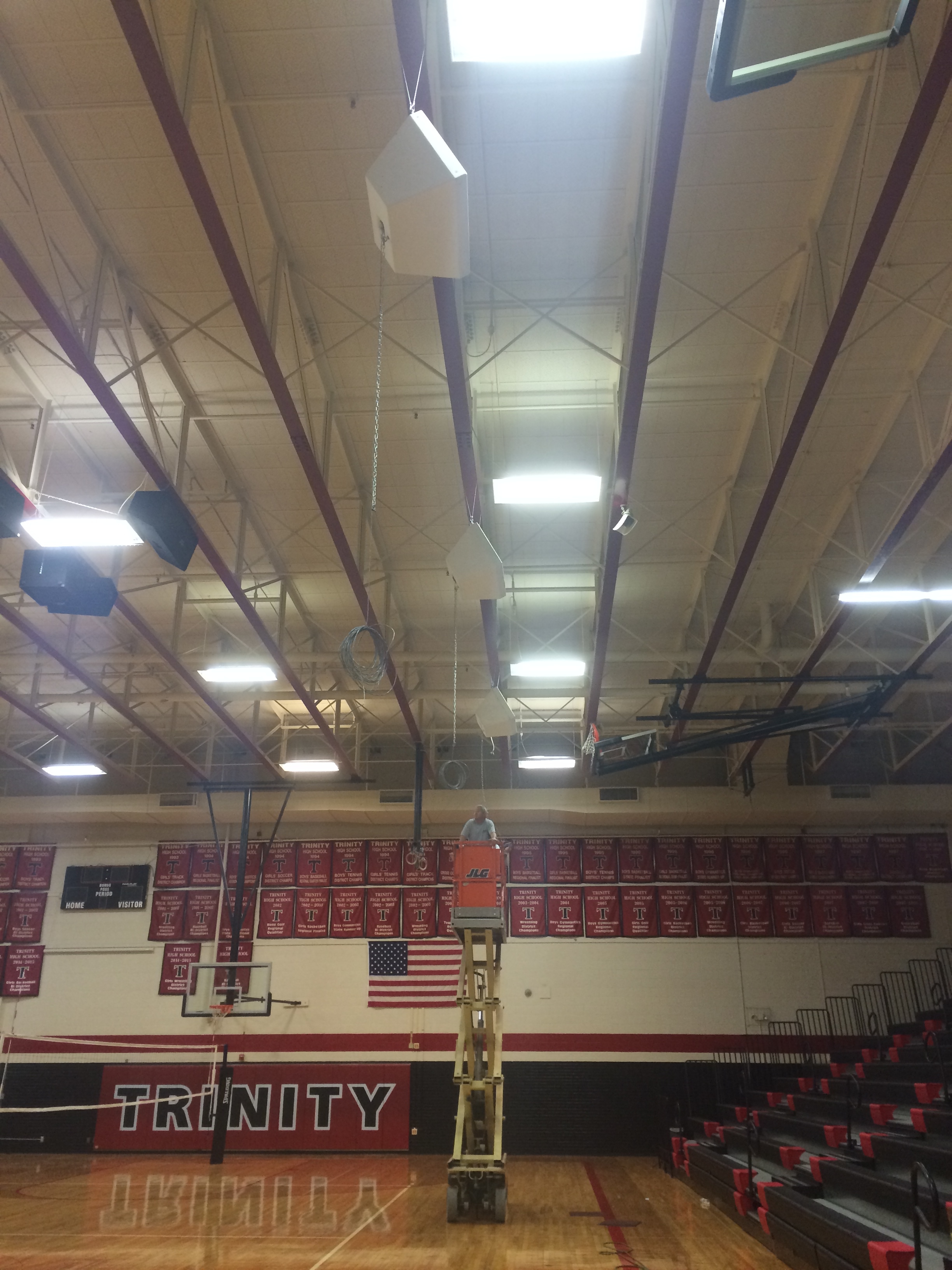
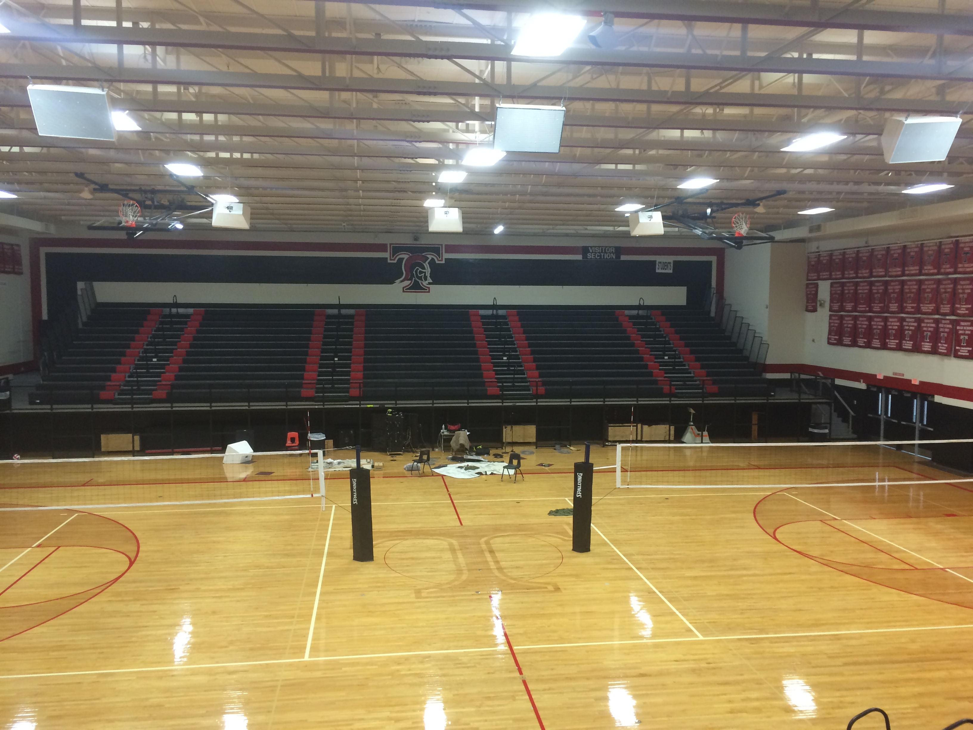
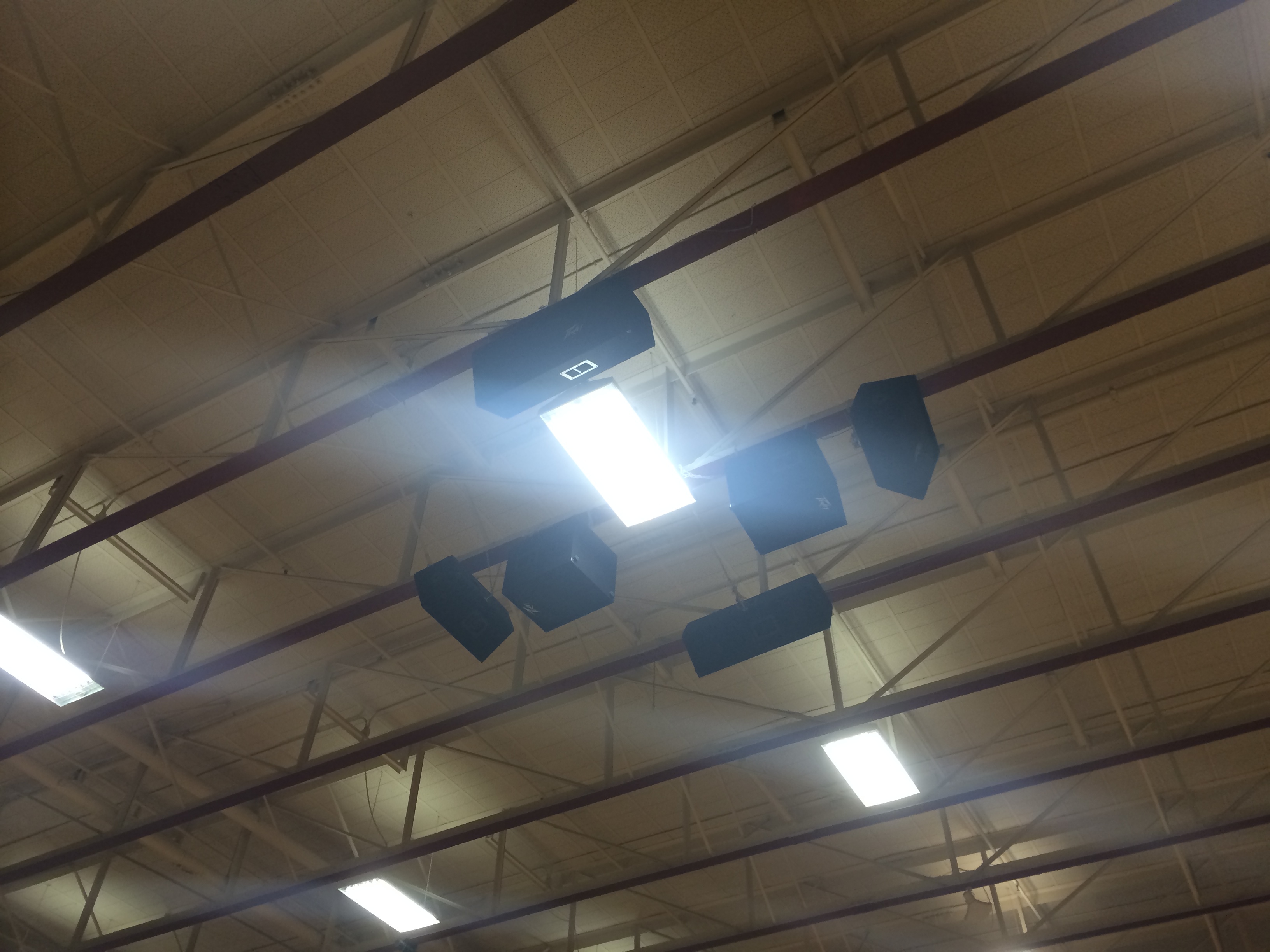
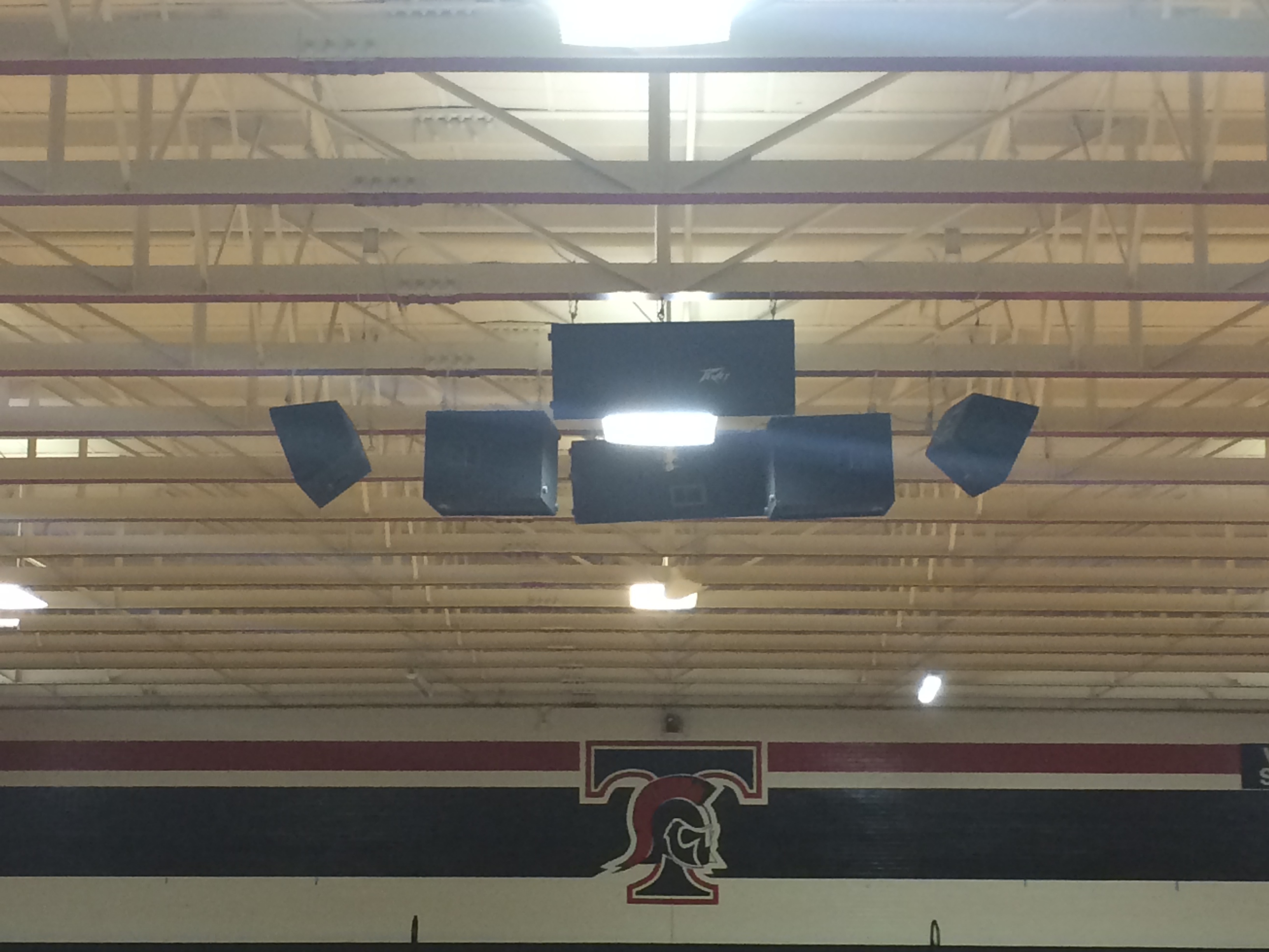
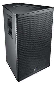
Years ago I helped a school replace it’s mono center cluster with some self powered QSC KW122 speakers configured as a R / L / R / L system.

The center of the old cluster was a JBL AS4735NW 3 way speaker. The NW has a passive crossover which allows it to be powered from a single amp channel whereas the STD version must be biamped.

JBL 4735 – spec sheet PDF
JBL 4735 – service manual PDF

The AS “architecture Series” is the install version (without handles but with rigging points). The same basic design is also available in the SR series is the portable version. In this case the SR cabinet is called an SR4735

JBL SR4735 – service manual PDF
Here is a product
JBL – SR series brochure

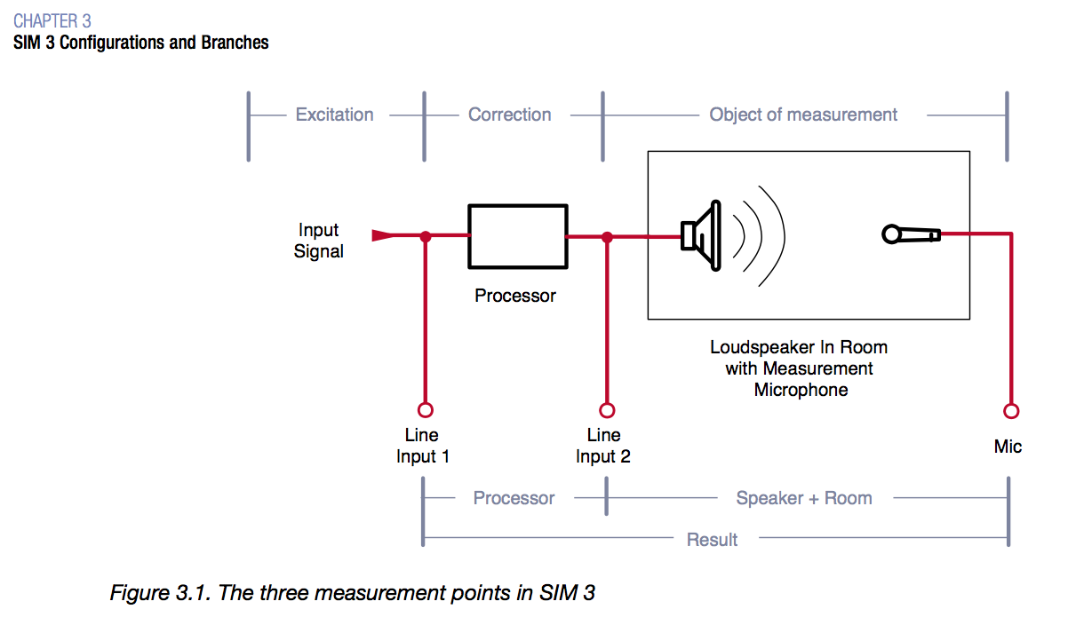
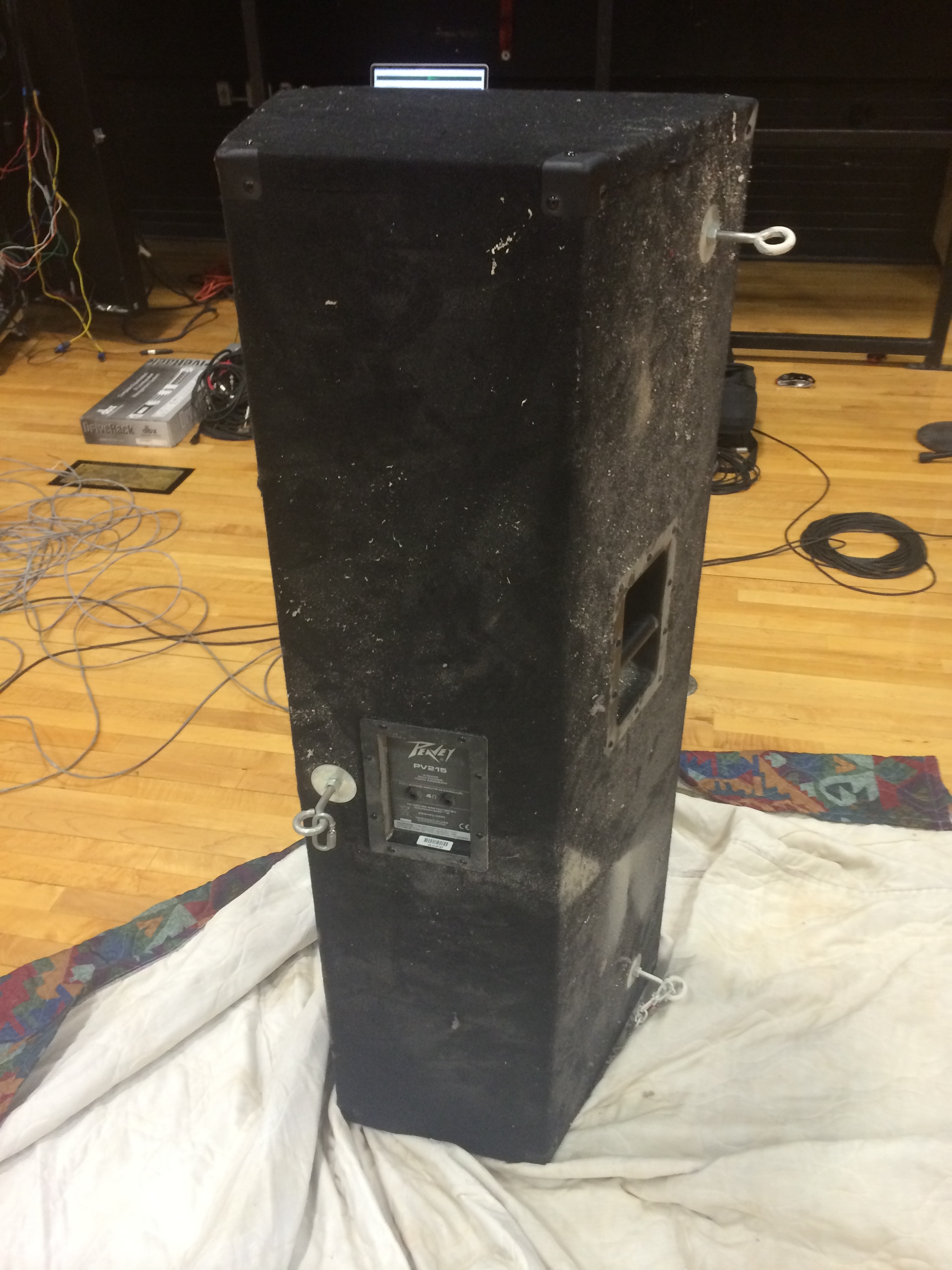
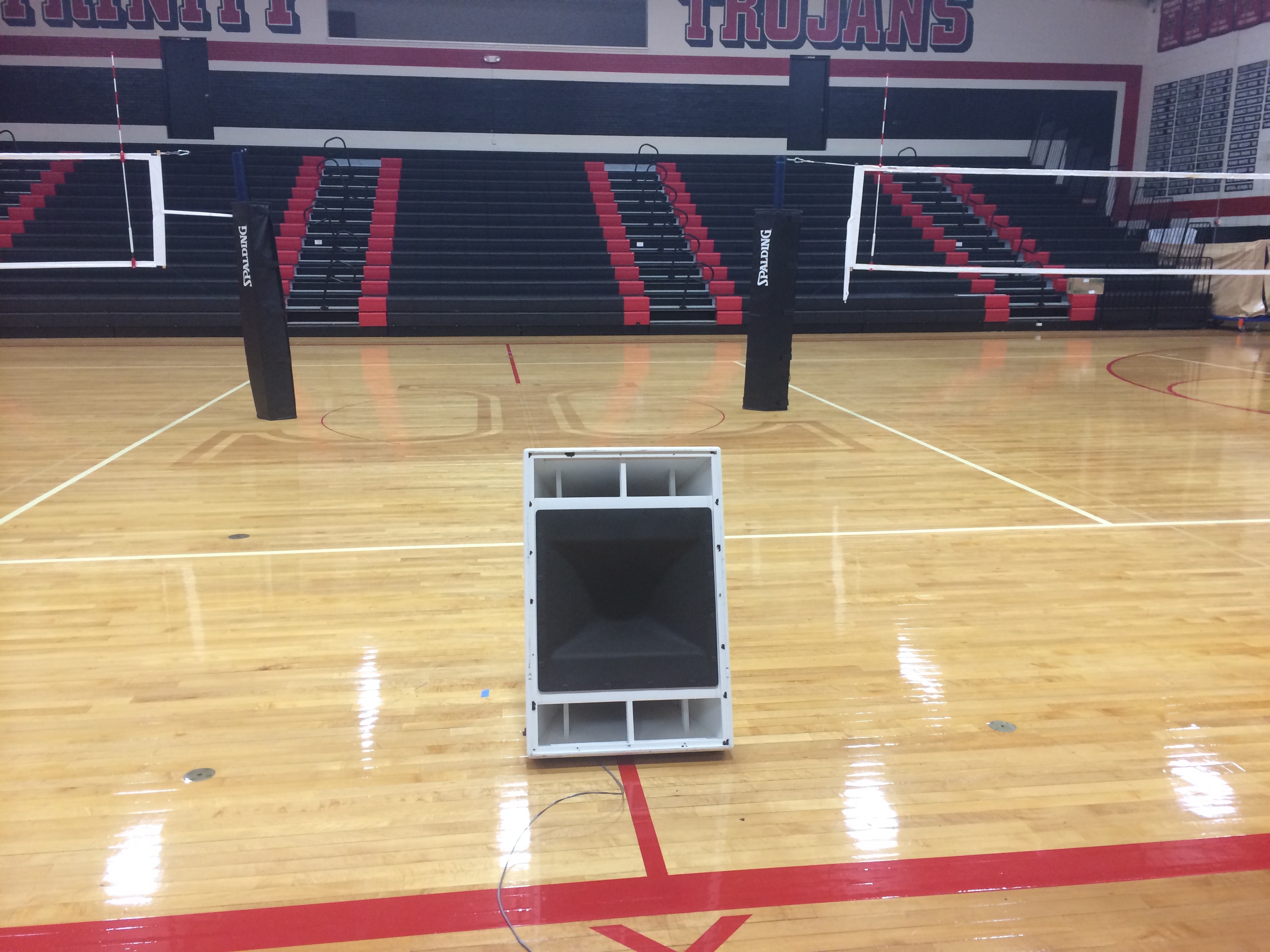
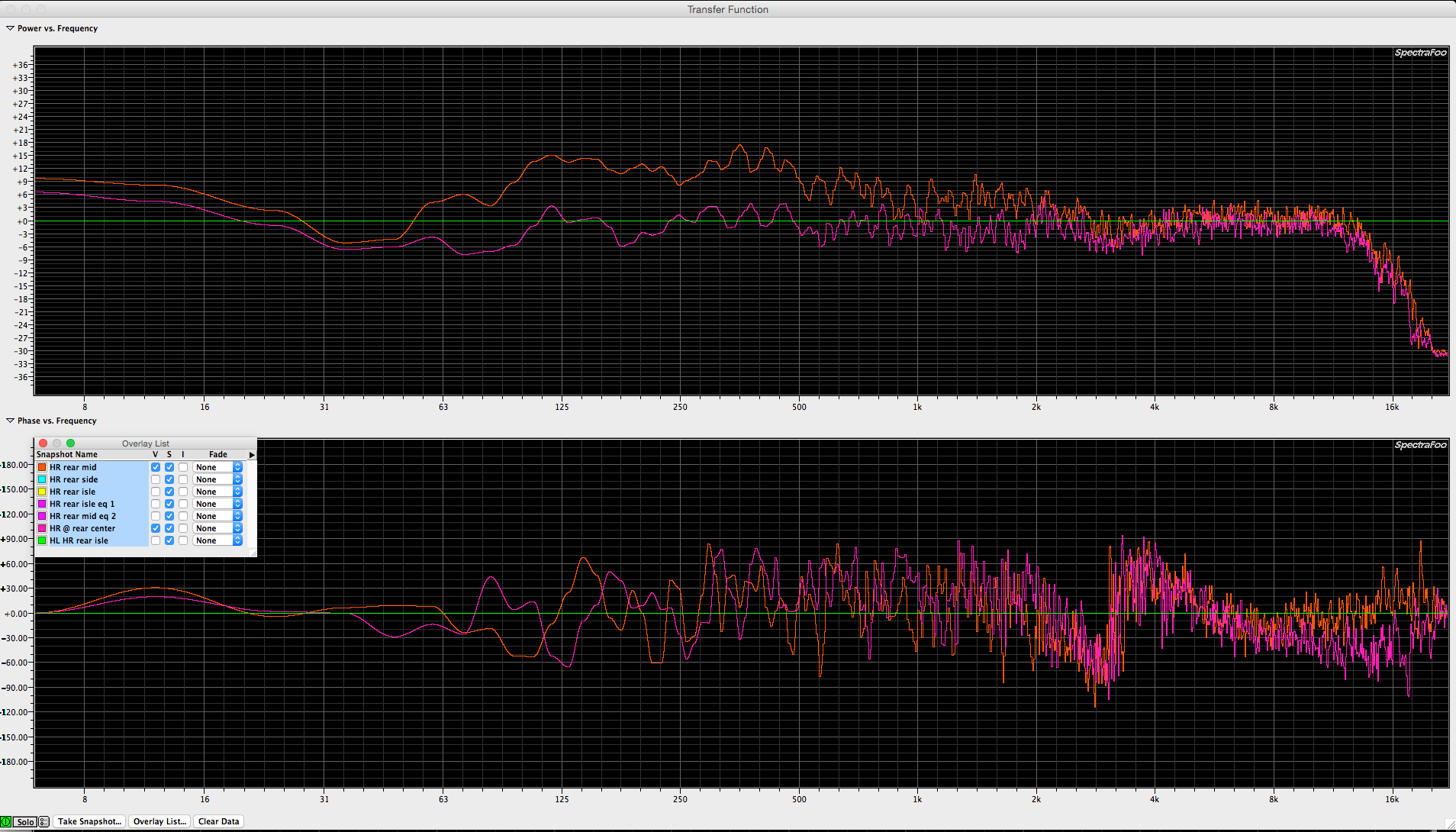
When it was taken down, it was put into storage and forgotten. Last year I tested it and discovered there was something wrong in the mid range. It went back into storage until today when I dragged it out again and remeasured it. When configured for passive crossover use, the cross over frequencies are 600hz and 2800hz. When configured for biamp use, you feed the LF 15″ driver directly an the MF / HF passive crossover covers that frequency transition.

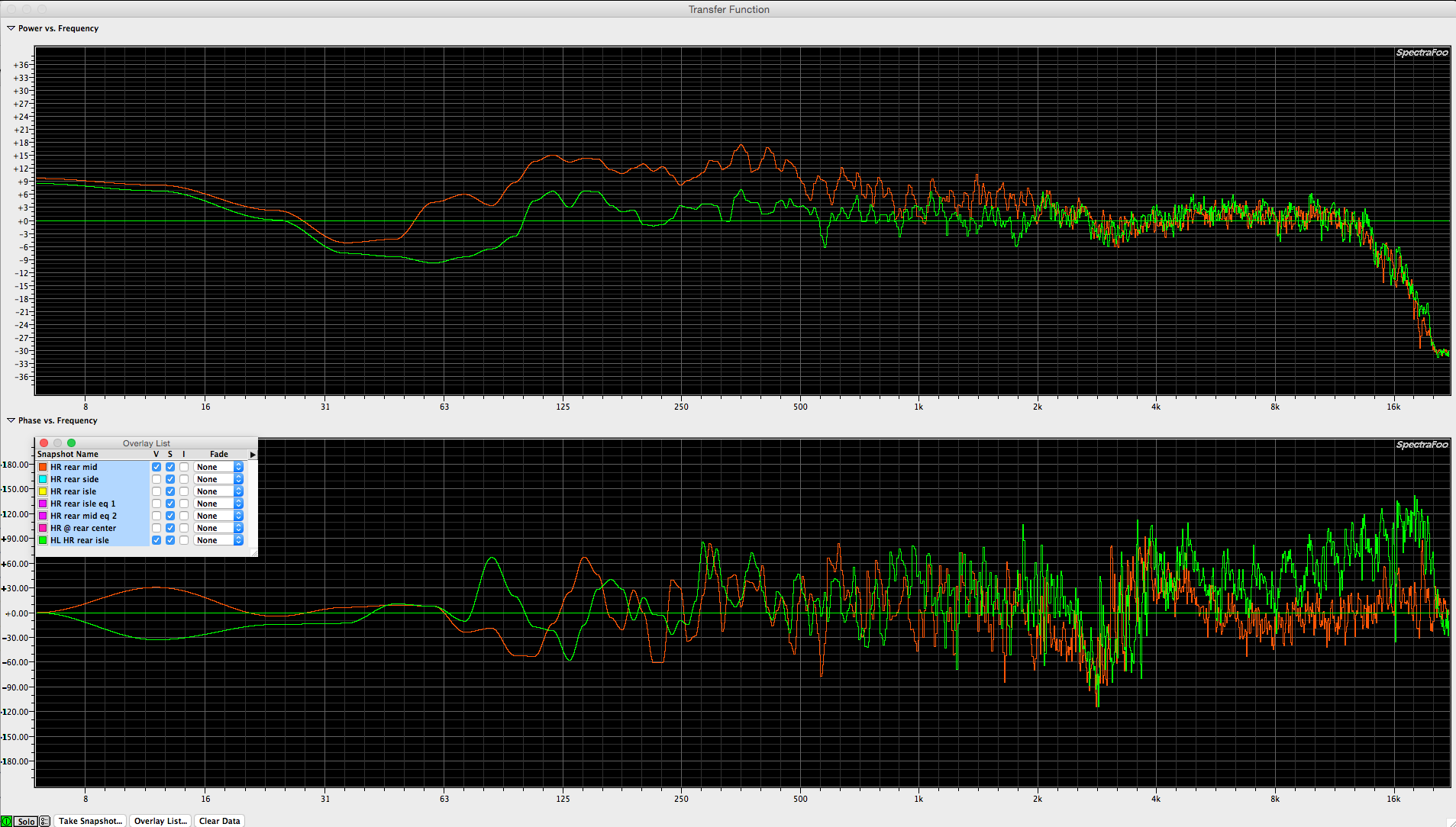
Here is what the cabinet measures like AS IS.
This is a measurement with the LF driver unplugged
This is a measurement with the LF & MF driver unplugged (HF only)
This is a measurement with the MF driver unplugged (LF & HF)

In removing the 8″ MF driver, I discovered a few things. First, it’s housed in a sealed box inside the cabinet. Secondly, the paper cone has broken almost completely loose from the piston which explains why most of the mid range are mostly absent but not completely absent.

Having done some recent measuring at a venue with some passive 3 way cabinets (separate amp for each speaker & separate processing) and realizing how little I understand about how to configure an active crossover (analog or digital), I thought that once this JBL AS4735NW is @ 100% again, I can do some modifications to it to make it possible to easily turn the (3) speakers on and off externally. Also to choose between the passive crossover and an active (3) way setup. It will require some switches and rewiring but should make it possible to quickly test and understand what does what. How does a 3 way speaker behave and measure when the (3) drivers are in polarity and out of polarity? How does changing the crossover frequencies affect the sound of the loudspeaker?

My hope is that once I have seen how everything works in a controlled environment and I understand what to expect when things are wired correctly and incorrectly, I will be better prepared to recognize the same attributes in the field. If I need to verify a speaker after replacing drivers or discover something strange, it would be helpful to know that I’m on the right track and not chasing my tail.

If you can’t tell what is what working with a 2 way passive box, there is little hope of managing a 3 way active rig. I’m still in the “lots of questions” category of understanding a 2 way passive box.