I just came across an interesting article called,
Meyer Sound – Frequency Response Measurements and the
Meyer Sound HD‑1 High Definition Audio Monitor
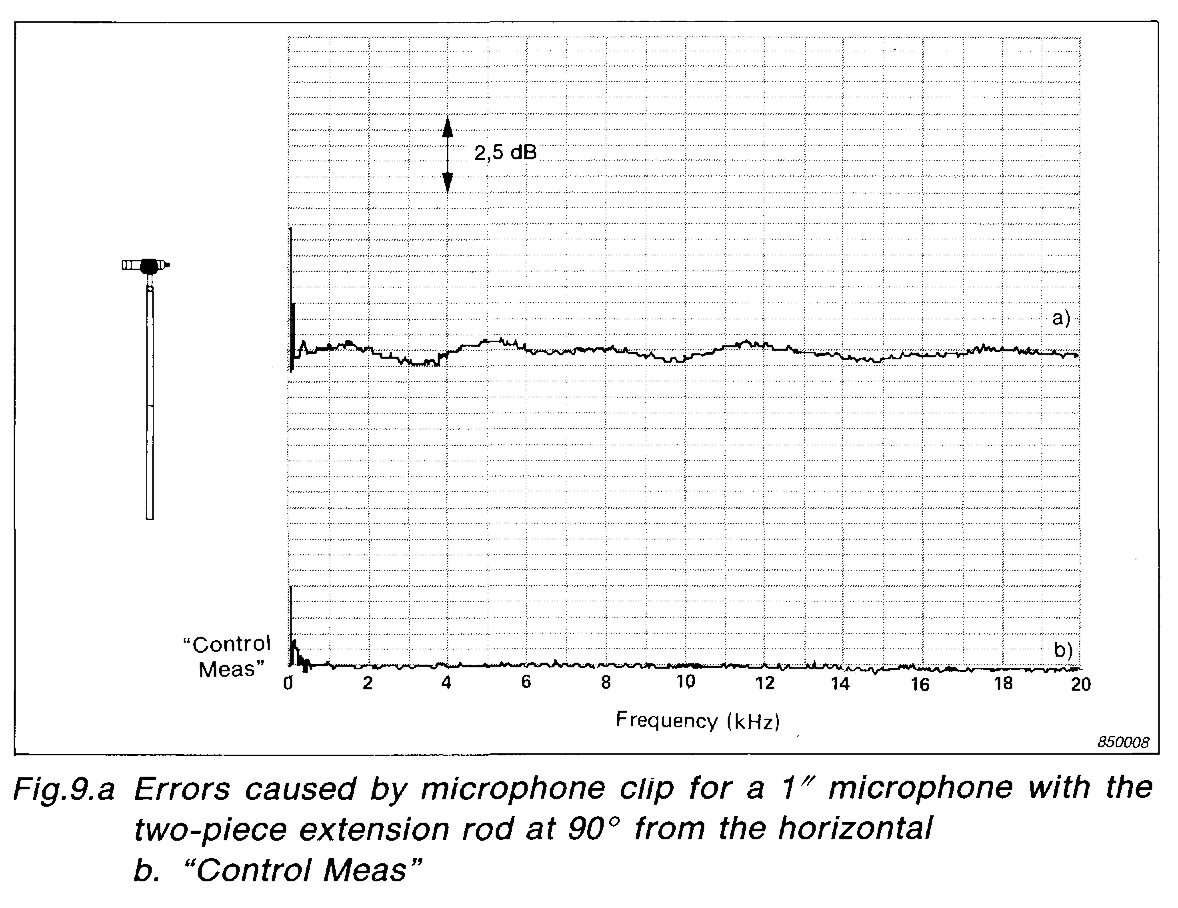
A truly fascinating read but the following diagram on page 7 really stuck out:
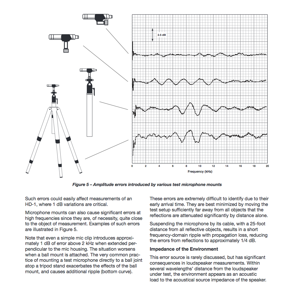
We must be careful about how we place our mic clip on our measurement mics, what type of clip we use and where our stand is.
This reminds me of a conversation I had with Eric Blackmer of Earthworks Audio years ago. He explained that there is a measurable different between locating the mic clip at the very back end of the mic and forward closer to the tip. I hadn’t really given this idea much thought but the diagram reveals just how important the clip type, orientation, mic stand type, boom arm angle and placement really is.
In fact Earthworks staff wrote a paper that explains how they measure their mics:
Here is a relevant quote from the white paper on PDF page 5:
” Attention must also be given to the microphone’s mounting.
Microphone clips should be placed as far from the tip as possible. I even use an absorptive material around
the microphone stand to eliminate reflections. Although Earthworks microphones have the stepped shape,
the step is very gradual and the reflections due to its presence are about 40 dB under the signal (actual
measurement).”
The white paper goes on to state the following on page 6:
“Many measurement microphones have some kind of slotted cap covering the diaphragm. This cap is often
used to shape the frequency response, as well as being a protective cover. Unfortunately, it is seldom a
minimum phase equalizer, and tends to degrade the original impulse response of the microphone element
by creating a complex set of reflections. In addition, many measurement microphones have an oversized
rear chamber with significant internal echoes.
These echoes make impulse response anomalies even worse. All this results in time-domain measurements
being seriously compromised. We have studied 1/4″ measurement microphones by B&K and Gefell, and
concluded that the only meaningful way to use them was to take the caps off. Then, even the
exposed threads had an influence on the response! And I had to cover the threads to bring the
measured responses closer to those specified by their manufacturers. The reason for this is that the
supplied response curves of the microphones are not actual acoustic measurements. The manufacturers use
an electrostatic actuator and a correction curve for presumed effect of microphone shape to obtain a
response chart for their microphones, a method that has no means to reveal the influence of anomalies in
the external acoustical structure. It’s a bit like deriving the response of a finished loudspeaker from the
responses of its components instead of measuring it.”
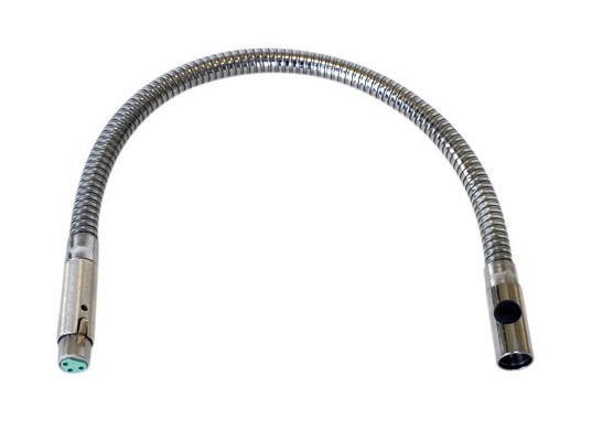
Take a look at Earthworks measurement mic. No near reflections with that one 🙂
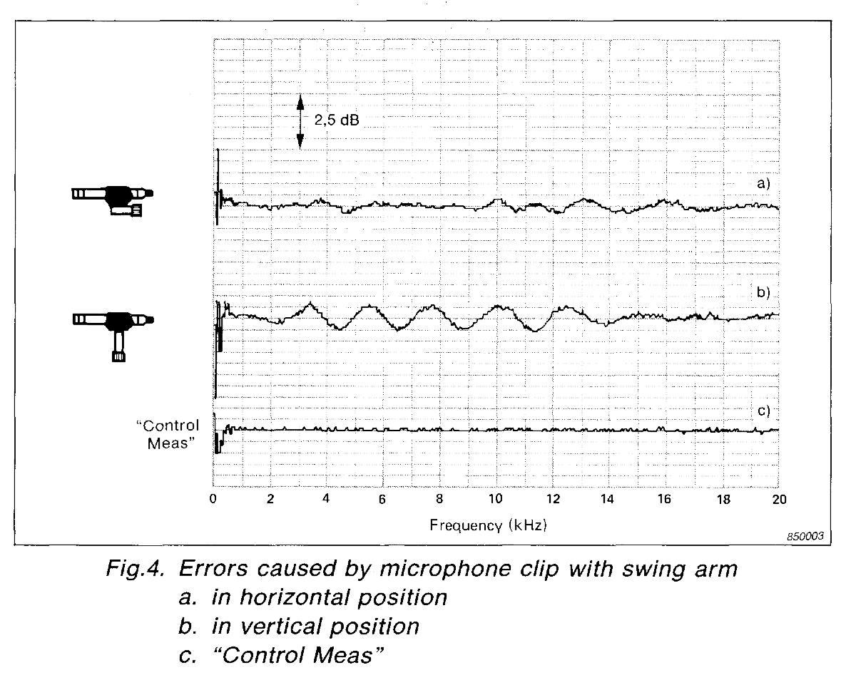
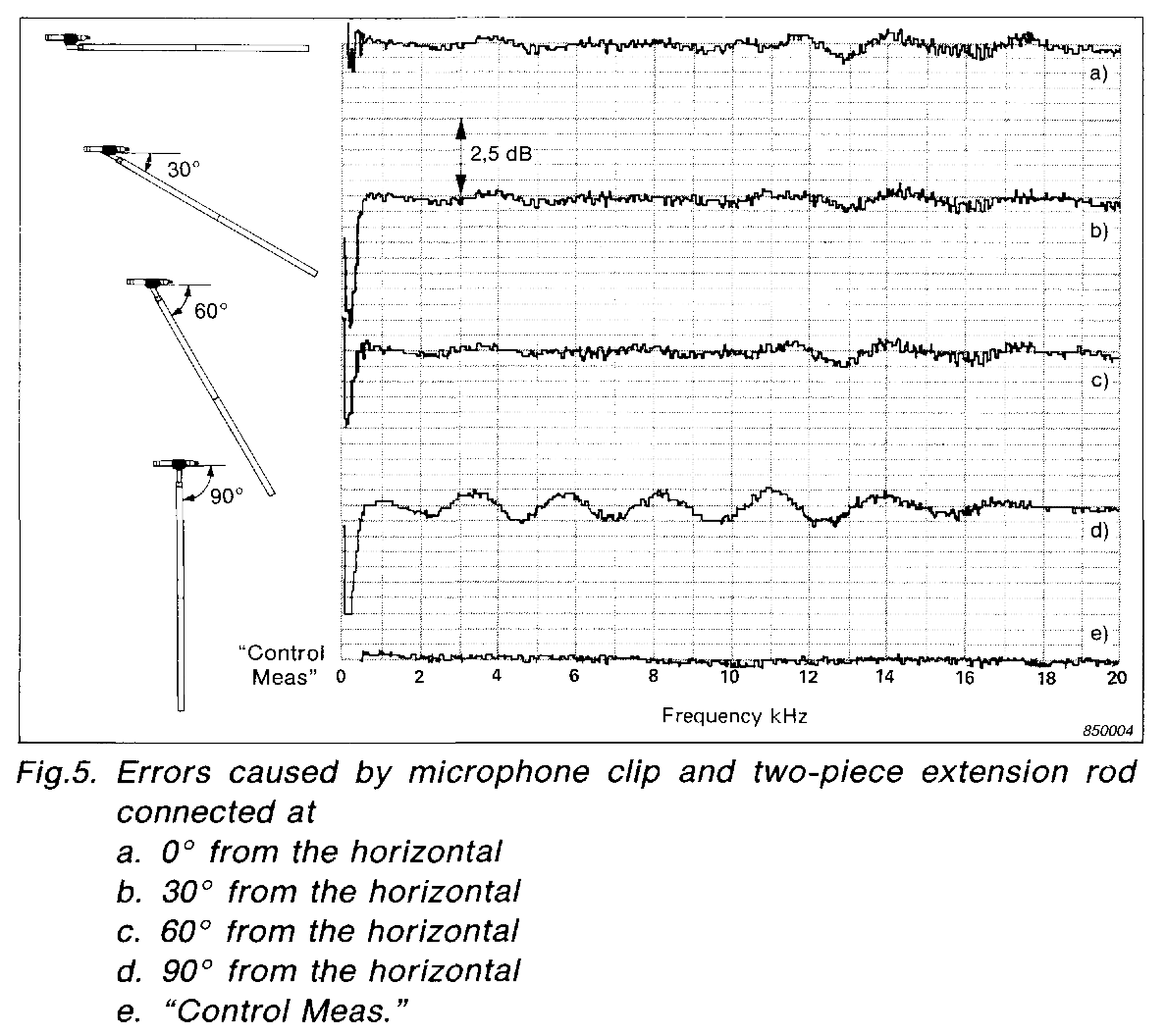
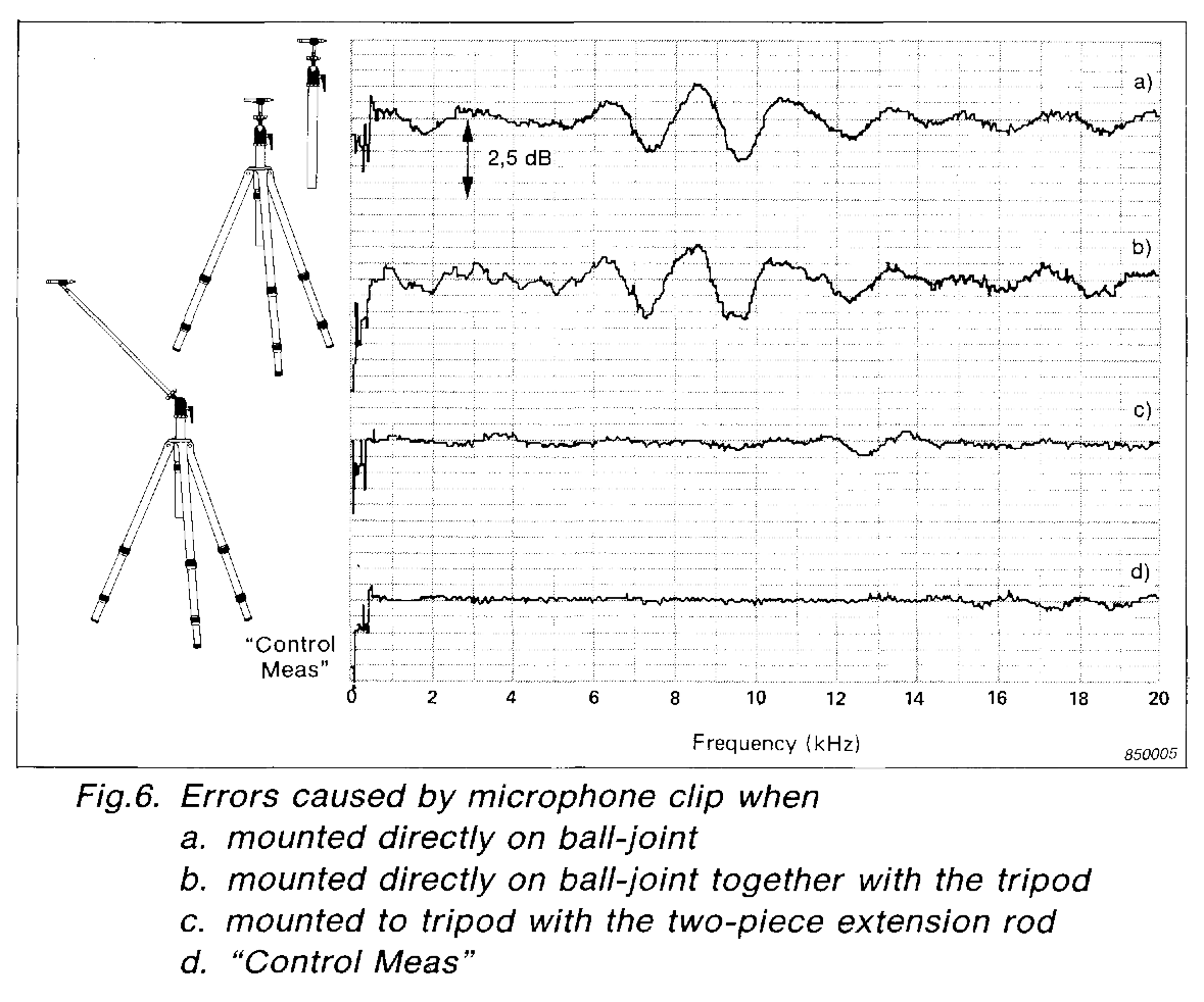
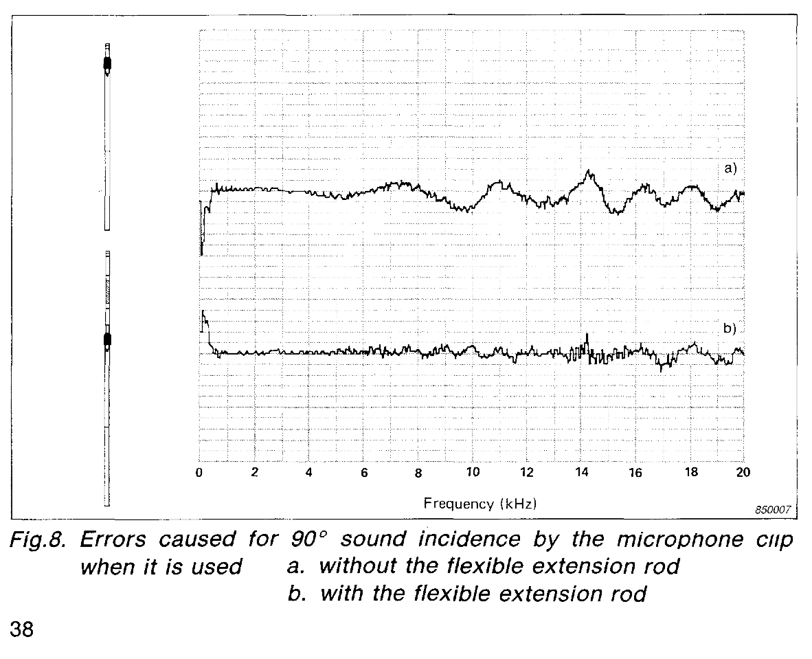
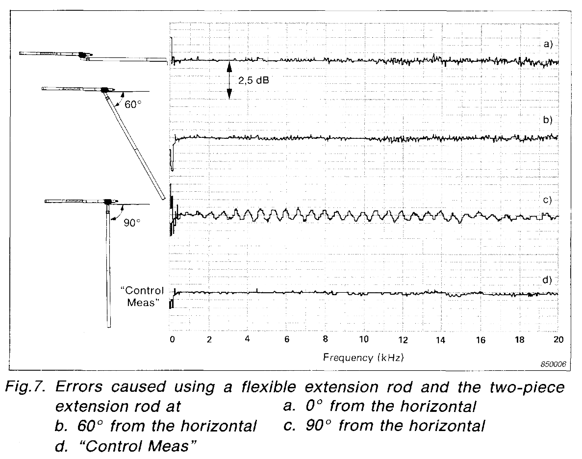
Come to find out the original source of the diagram referred to in the Meyer Sound document is taken from a B&K article published in 1985. The article starts on page 32 (PDF 34) and ends on page 39 (PDF 41)
Validity of Intensity Measurements: Influence of Tripods and Mic Clips , Brüel & Kjaer Technical Review no. 4 (1985)
Here are some additional diagrams that should drive the point home…
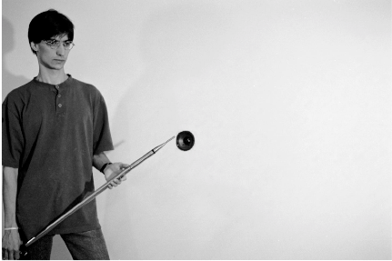
I just ordered one of these and will do some experiments myself and then report back with my results.