I’m back in a local Dallas venue that has a Fulcrum Acoustic sound system.
The system consists of:
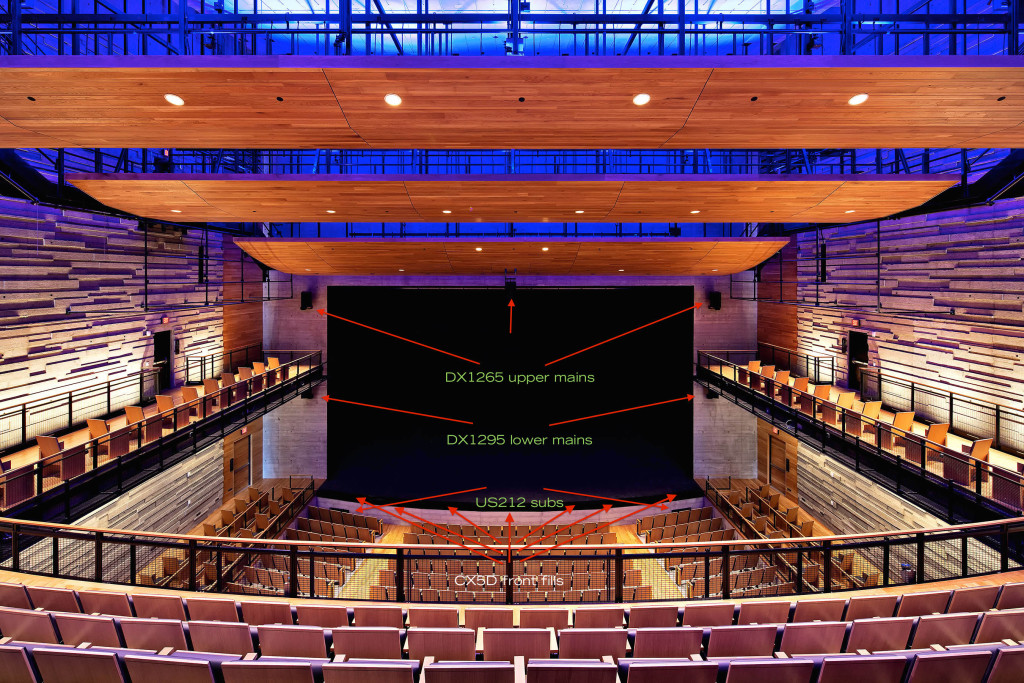
(2) DX1265 for upper main L / R
(2) DX1295 for lower main L / R
(4) US212 subs located in cavities under the stage.
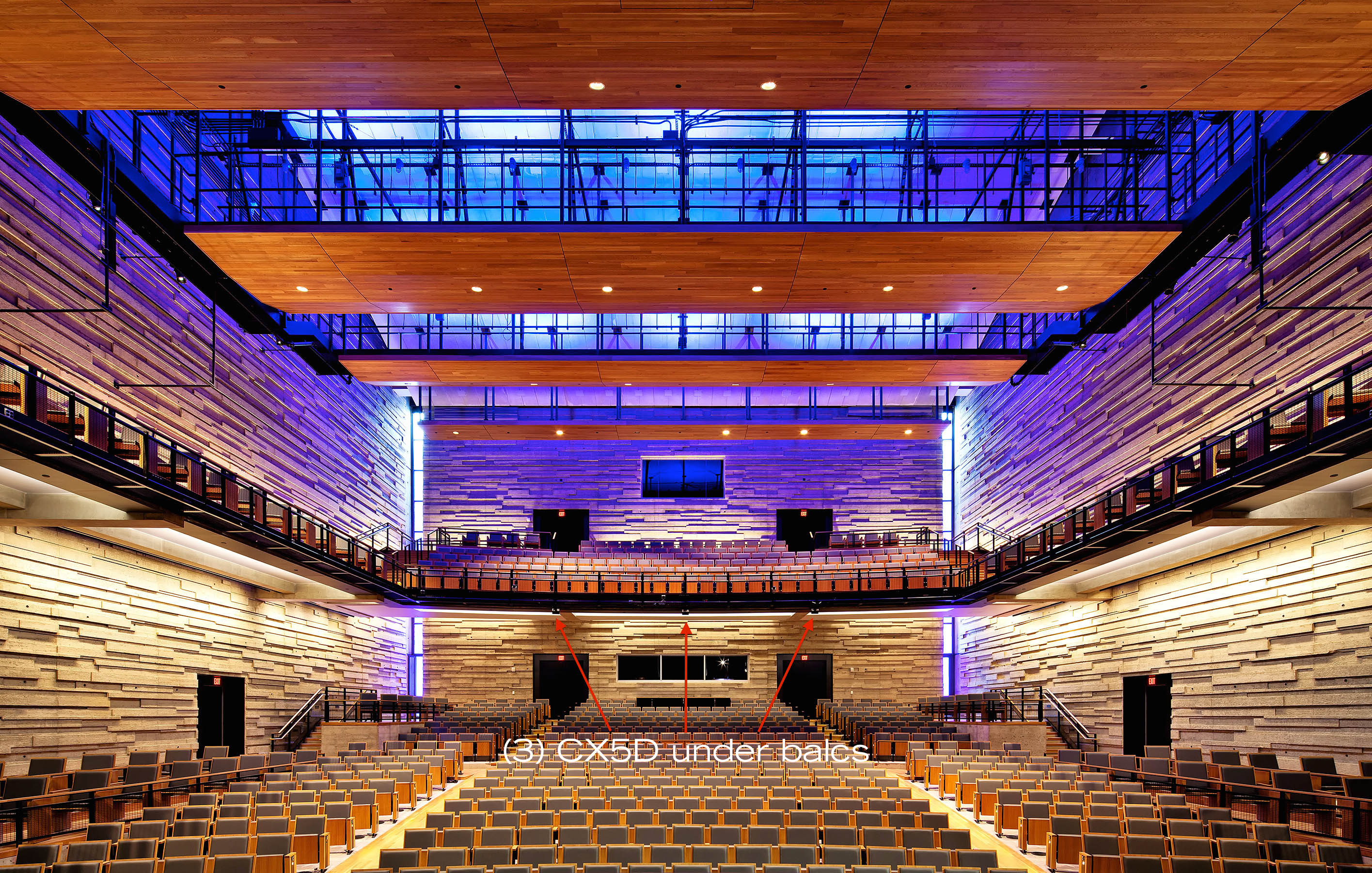
(3) CX5D for under balcony fills
(7) CX5D in the face of the stage for front fills
There is a center cluster that is not a Fulcrum product.
(1) D&B TI10L 5 box line array center cluster
d&b audio – Ti10L webpage

This is my 3rd visit to the venue with Texas Ballet Theater. Previously I have known that the system wasn’t optimized but didn’t know enough to know what to do about it. I also didn’t have a relationship with the house crew to start digging into their settings. I have simply measured and Eqed at the board as best I could.
This time, there is enough trust between myself and the house crew to get into the DSP settings and discuss what might be wrong and what might be done to make things better.
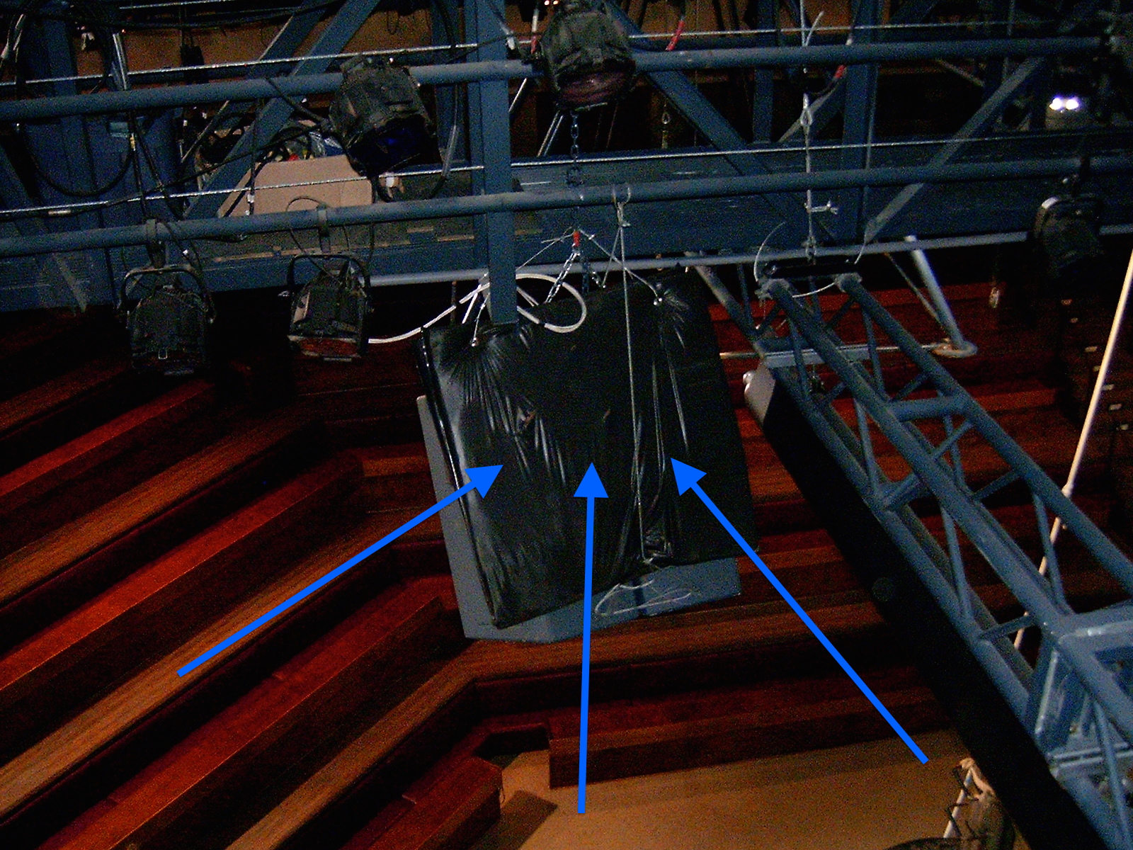
What are the issues? The PA appears to have issues of speaker placement and aim. Poor coverage on the sides, uneven response, uneven levels, overlapping coverage, possibly incorrect delay times, speakers that are reflecting off near by surfaces, subs located too close to specific seats, subs mounted in resonant chambers, etc…
If the proof is in the pudding, it simply doesn’t sound very good. The good news is that I think the existing system can be greatly optimized with proper aim & correct processing. Neither of which requires much effort and cost to correct.
Since I haven’t finished gathering the necessary information to go forward with the verification process yet, I’ll hold my final judgement but in the meantime, here are some interesting images…
This is the DSP block that is processing one of the DX1265 cabinets.
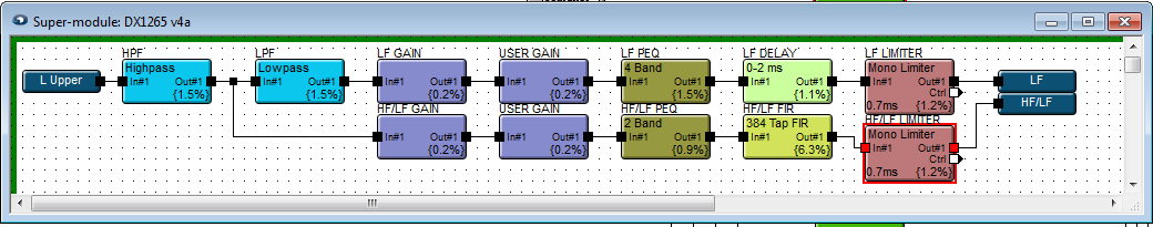
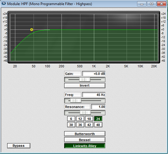
HPF
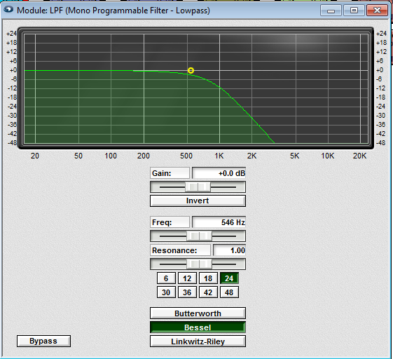
LPF
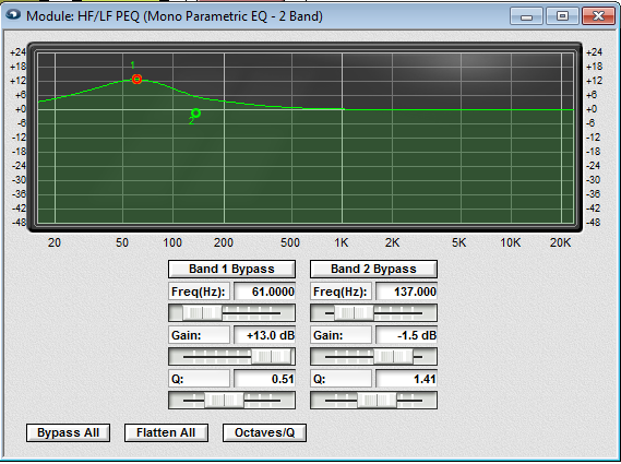
LF EQ

HF / LF EQ
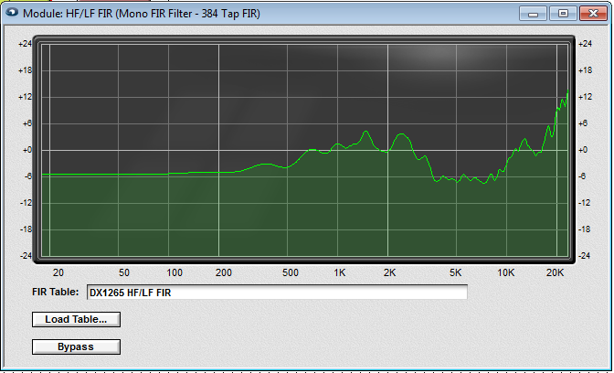
HF / LF FIR (Finite Impulse Response)
WIKI article – FIR / Finite Impulse Response
This is interesting,
The upper DX1265 Main L / R boxes have a delay between the HF/LF & LF driver of .438 ms:
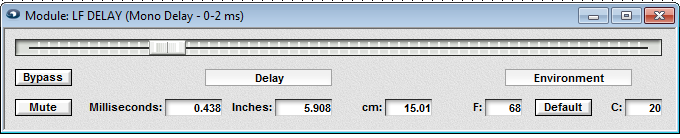
The lower DX1295 Main L / R boxes have a delay between the HF/LF & LF driver of 1.479 ms:

Same box, same dual 12″ LF drivers. The DX 1265 has a 60 x 45 horn. The DX1295 has a 90 x 45 horn. What accounts for the 1 ms+ difference in delay times between lower and upper boxes (between the LF and HF / LF drivers) ???