
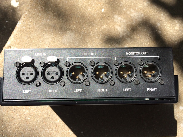
I’ve been looking at XLR Y splitter boxes for my measurement rig for some time and when I saw a stereo Avid Audio Splitter listed on EBAY, I ordered one. The cost was around $20 and I couldn’t build one for much less than that (ignoring labor). I didn’t know what to expect inside the box but there is no power connection so the device is obviously passive. Regardless of the circuitry, I could modify the box if necessary. The device has the following connections:
LINE IN (Left / Right)
LINE OUT (Left / Right)
MONITOR OUT (Left / Right)
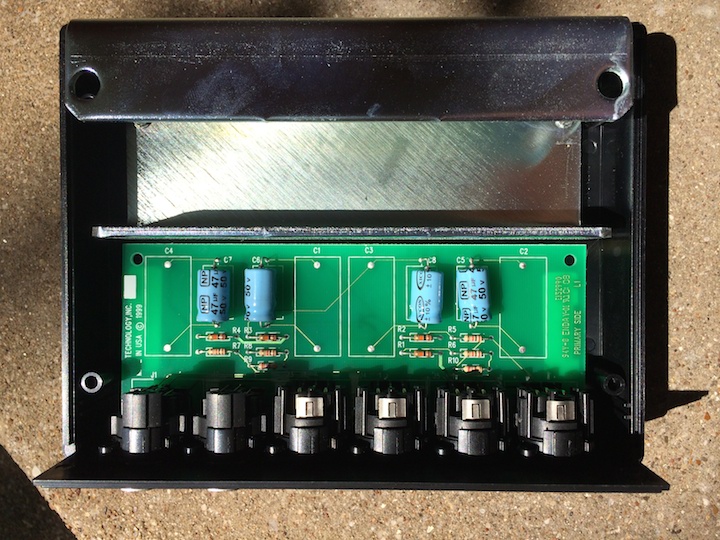
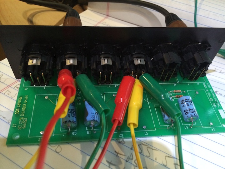
Of special interest is the massive metal piece inside the box that serves no purpose other than to add weight to the device. Everything else is plastic so it must of been decided to add the weight to keep the box from falling over from the weight of (6) XLR connectors. Counter ballast if you will.
I checked the circuit board and the LINE IN to LINE OUT connections are parallel connections (straight wire). I had hoped that the MONITOR outputs were also parallel connections but instead there are some passive components involved in that signal path.
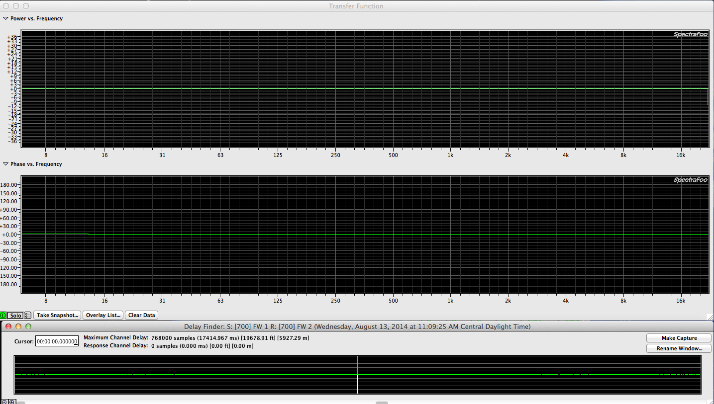
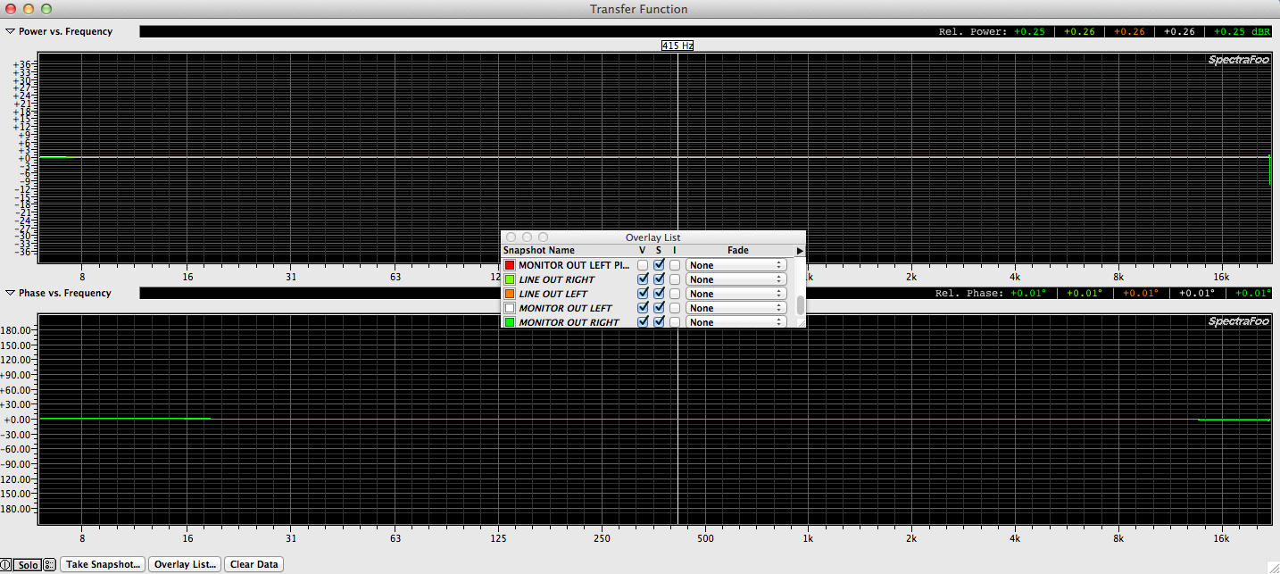
Here is the trace when I measure the LINE IN to LINE OUT path. Note the perfect impulse response as well as perfect frequency and phase response. What we would expect from a piece of 3 conductor wire with connectors on the ends compared with another piece of 3 conductor wire with connectors on the ends.
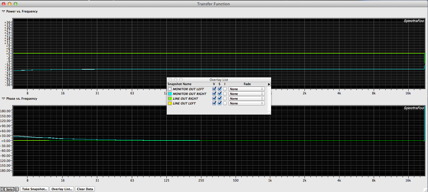
What do the resistors and capacitors do in the MONITOR OUT circuitry? Here is a trace of the LINE IN to MONITOR OUT path
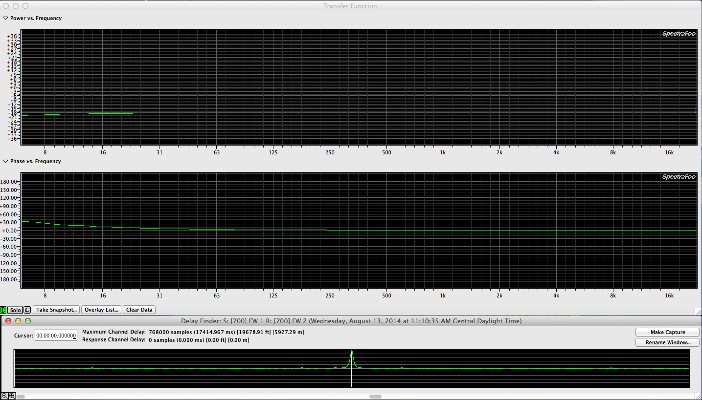
Together, the capacitors and resistor networks cause an 18db reduction in gain and some low end phase drift (due to the capacitors). The capacitors also appear to elongate the impulse response. Certainly not what I want to use as a reference point!
Here is a overlay of all (4) snapshots. Left / Right traces match but there is the same -18db reduction in gain.
Since the goal is to have a stereo 1×2 splitter box with parallel connections, I’ve installed some wire jumpers across the LINE OUT and MONITOR OUT XLR pins which in theory will bypass the resistors and capacitors.
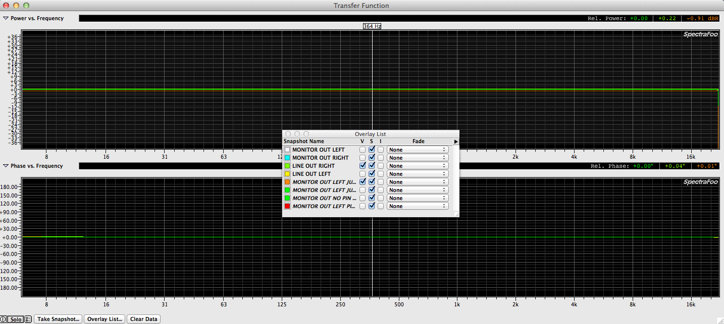
Here is a measurement overlay between the original LINE OUT and the MONITOR OUT with the jumpers installed between LINE OUT and MONITOR OUT pins. Identical.
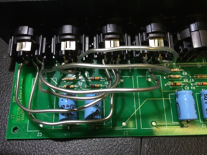
Now I’ll install permanent jumpers between the LINE OUT pins and the MONITOR OUT pins and put this box back together. I’m using buss wire which is solid and relatively non flexible for the connections.
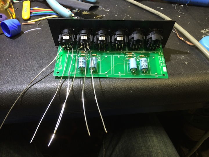
I’m also using clear shrink wrap to avoid any shorts. I shouldn’t need it if I bend the buss wire correctly but I have the shrink wrap and it can’t hurt:)
Here is the device with (6) buss wires installed.
Let’s measure again to verify we have achieved the desired goal.
(4) snapshots that overlay perfectly. I’m going to put the device back together and move on…