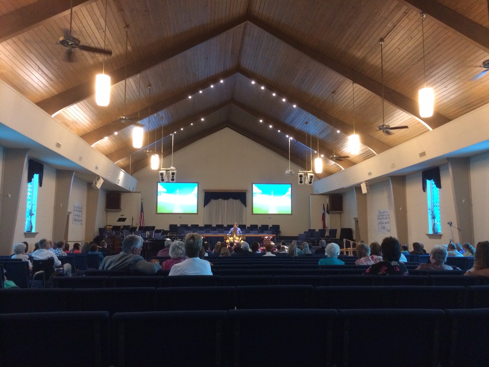
I got an emergency call on Friday to go help a local venue who let their house audio engineer go. With 3 overlapping high profile productions coming in, they wanted someone who had been in the venue before & I have spent a few months of time over the course of the last 5 years working with the previous house engineers during my stays with the ballet company during Nutcracker season.
Upon arrival I was tasked with helping to resolve a few issues. One of which was trying to eliminate or at least minimize the noise on the wired Clearcom & wireless Telex communication systems.
The system consists of the following gear.
(4) Clearcom PS-704 (4 channel power supplies)
http://www.clearcom.com/download/user-manuals/ps-704-manual
(4) Clearcom RM-704 (4 channel remote stations)
http://www.clearcom.com/download/user-manuals/rm-704-manual
(2) Clearcom TW12B (2 channel comm isolation unit)
(2) Telex wireless comm systems (add details)
This system is rather complicated compared to what I have used before. In fact I’ve never seen comm patch bays before accept in this & facility & it’s adjoining venues. Here is the patchbay as I found it:
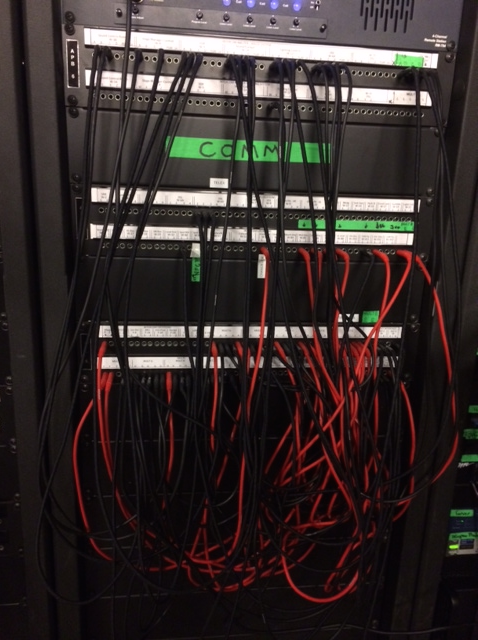
After soon careful thought & discussion between myself & the house staff, we started by simplifying the system to troubleshoot the noise.
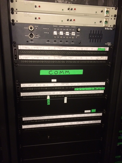
Literally every device in the system power/signal is supplied through the patchbay so pulling all the jumper wires meant that we could start with a single power supply & the remote station in the amp rack. Even a system as simple as this had 60hz hum present. We tried adding & removing different systems from the rig without any change in noise. It became clear that we were going to run out of time if we continued to troubleshoot & as they say, “noisy comm is better than no comm at all” so we (the house crew & myself) began to put things back together as best as we could. At the end of the process we had the whole system running on (1) power supply. Noisy but working.
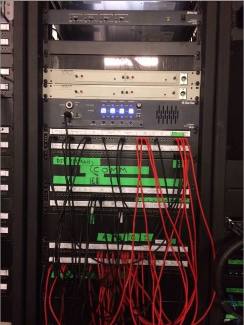
Doesn’t look much different than before does it? We did attempt to make any connections that would be considered “permanent” with red jumpers but we ran out before we got there.
During my time away from the theater I downloaded the manuals for all the hardware & read through them. One fact that I was looking for was how many devices can one power supply support.
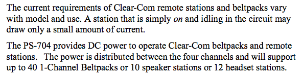
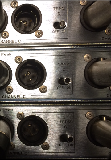
By reading the power supply manuals, I also learned that there is no termination option on the beltpacks, speaker stations or the remote stations. The only termination switches for the system are on the power supplies & only one should be terminated. In the case of the theater’s rig, all (4) power supplies were terminated which in some cases would be ok (if each power supply was powering a discrete system) but not with them all tied together at the patchbay.
When I returned on Sunday AM, I had a few things to try. For the sake of experimentation, I grabbed a ground lift adapter & headed for the amp room. When I arrived I discovered that (2) of the (4) power supplies were already lifted.
It couldn’t be as easy & taking them out of the system could it? Surely not. I removed them & tested again. The same hum.
The PS-704 manual clearly that there should be only (1) termination point on each system but that the system should be terminated. All (4) channels were terminated before my arrival & the system was still humming, I switched off all the termination switches…
All of the sudden the system was dead quiet.
Why?
Since it was Sunday & I couldn’t call anyone, I made a plan to contact Clearcom tech support on Monday & have a chat.
I wanted to know the rules for using multiple power supplies on the same system, why un-terminating the system made the noise disappear & what I should do to test things.
I called Clearcom & left a message. Then sent a long email with more details in case my call was returned by someone who got to read my email first.
support@clearcom.com
A short while later I got a call back from Clearcom.
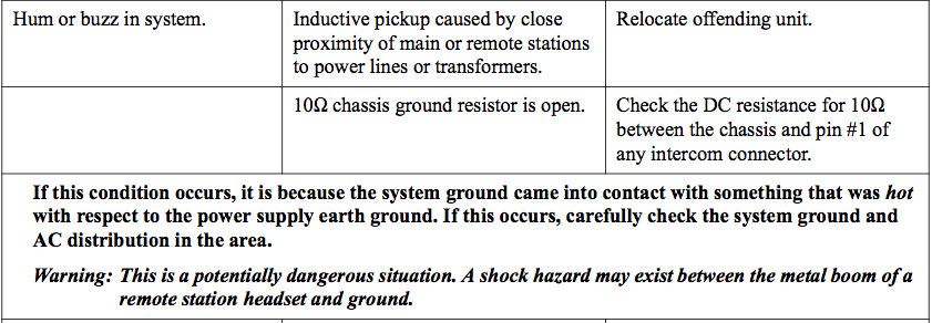
I explained the situation & learned some very helpful information. Most importantly is that if you short pin 1 to ground you blow a 10 ohm resistor in the power supply.
You may recall that the entire COMM system is on a mini TT patchbay. I had previously noticed that each time to make a connection on the patchbay there is a flash of light. (INSERT PHOTO or video of the arching)
Once I explained that our patchbays are TRS (tip / ring / sleeve) based patchbays, the Clearcom tech support person said, that is your problem.
His hypothesis was that all (4) power supplies had blown resistors since their first use.
When I arrived at the venue, I pulled (2) of the (4) power supply units out of the rack & opened them up.

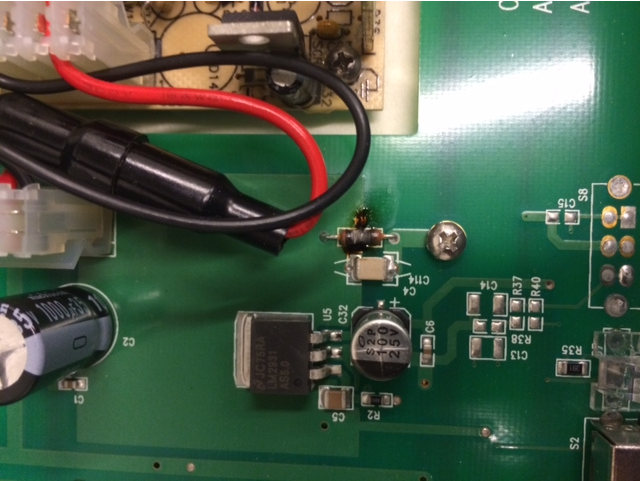
Is there any doubt the other (2) units aren’t blown?
Me – “Could this cause the hum?”
Clearcom tech support – “Absolutely”
So what is the solution?
3 choices.
1. ignore the noise, ignore the blown resistors.
Since visiting clients constantly complain about the noise I think we have to ignore this option.
2. Never make a termination at the patchbay without turning off all the power supplies. Can you picture trying to coordinate everyone taking their headsets off ever time you want to patch in another beltpack or change a channel assignment during a tech rehearsal? I think we have to ignore this option too.
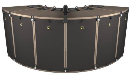
3. Ditch the mini TT patchbays & switch to XLR patchbays. Like this:
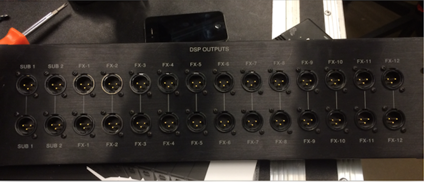
With an XLR patchbay, you can’t short the conductors as the jack & plug mate together. XLR also has the advantage of being a locking connection if you use the right jacks.
So the lesson to be learned is as I see it is this:
1. Don’t accept noisy comm
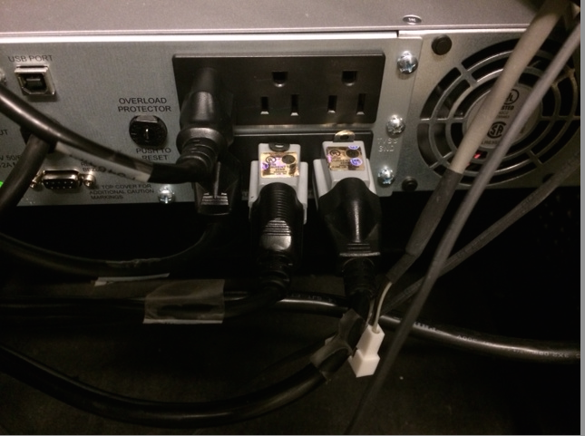
2. Don’t lift grounds on A/C connections (illegal & in this case didn’t help anything)
3. Don’t use TT (TRS style) patchbays for comm
4. Actively learn about things you don’t know
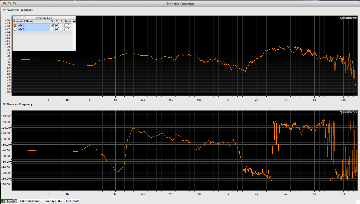
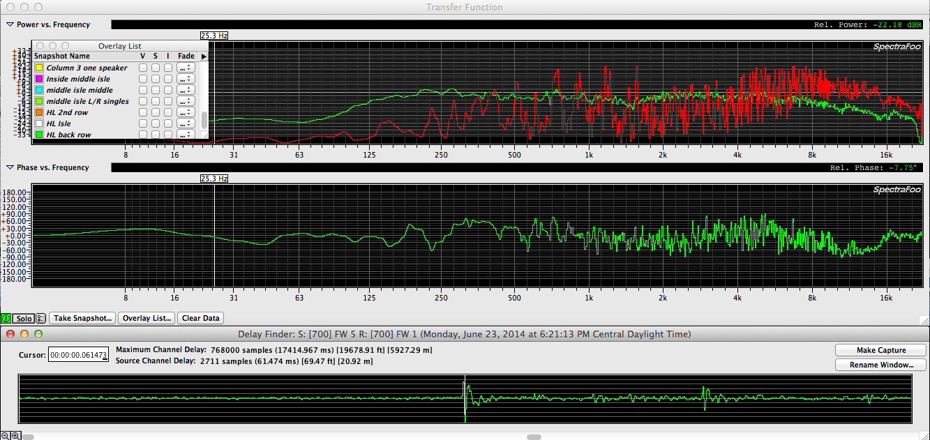


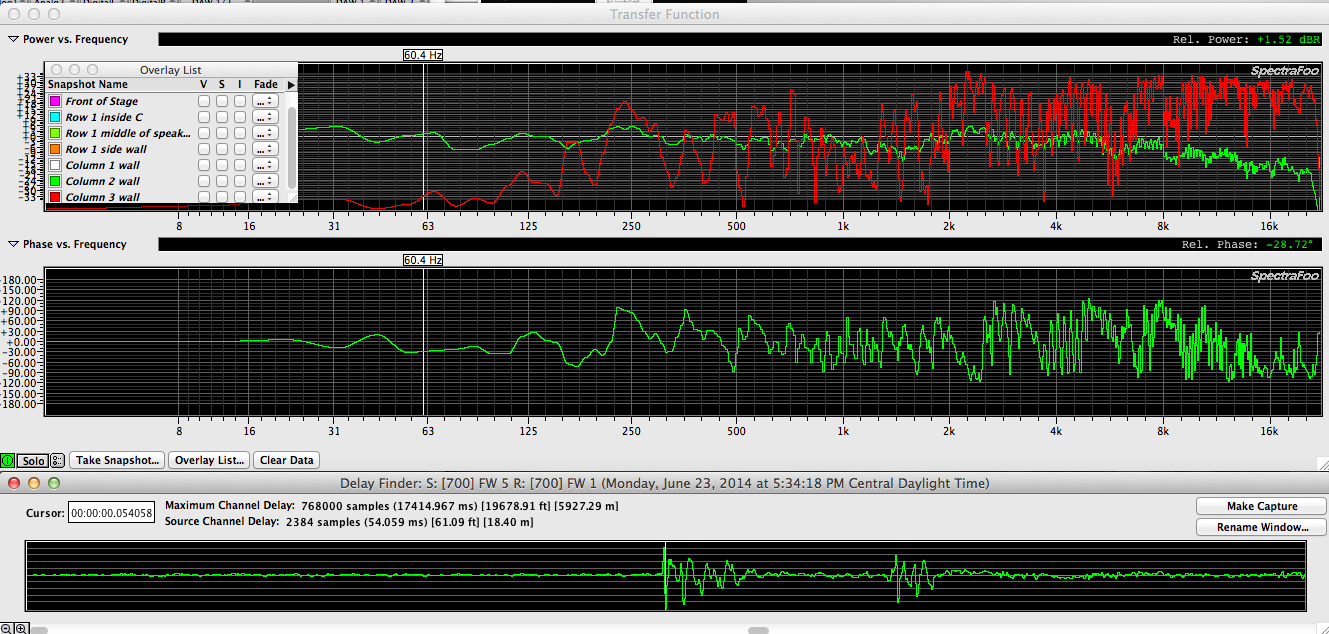
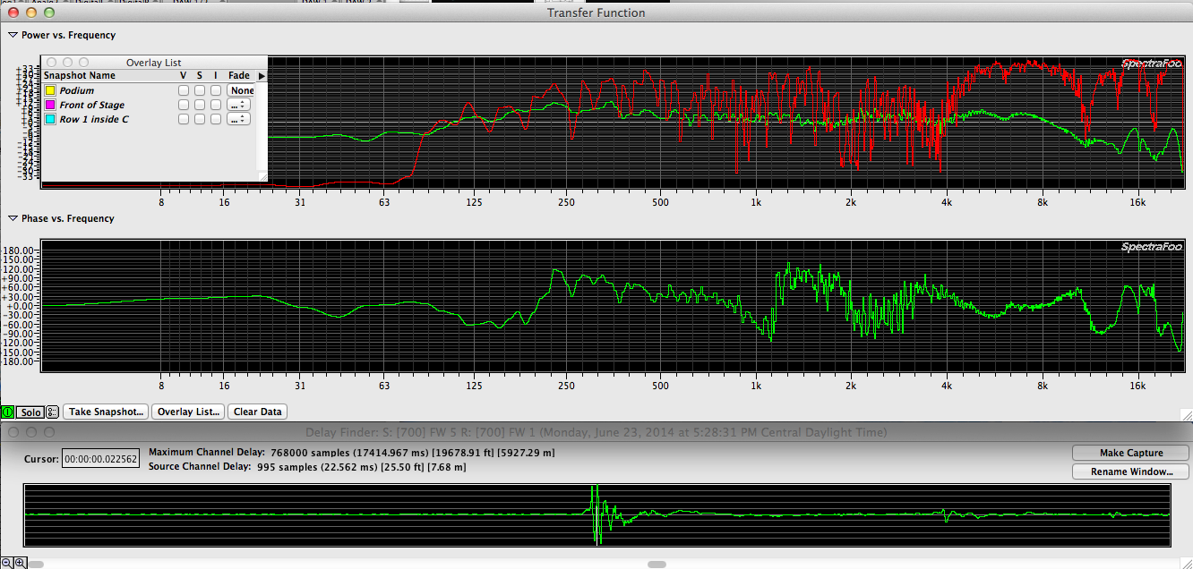
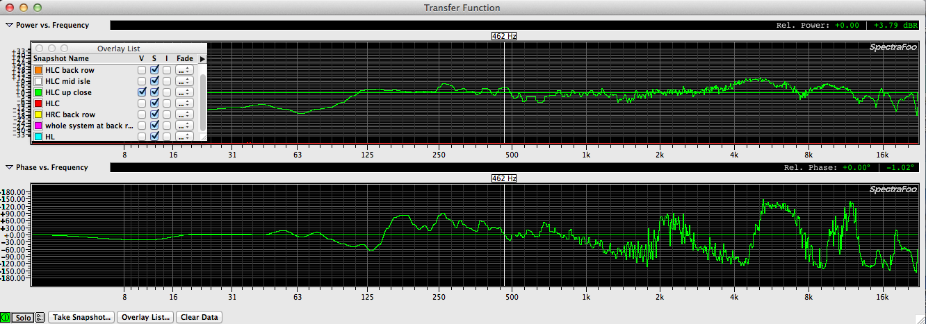
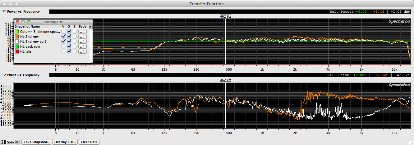
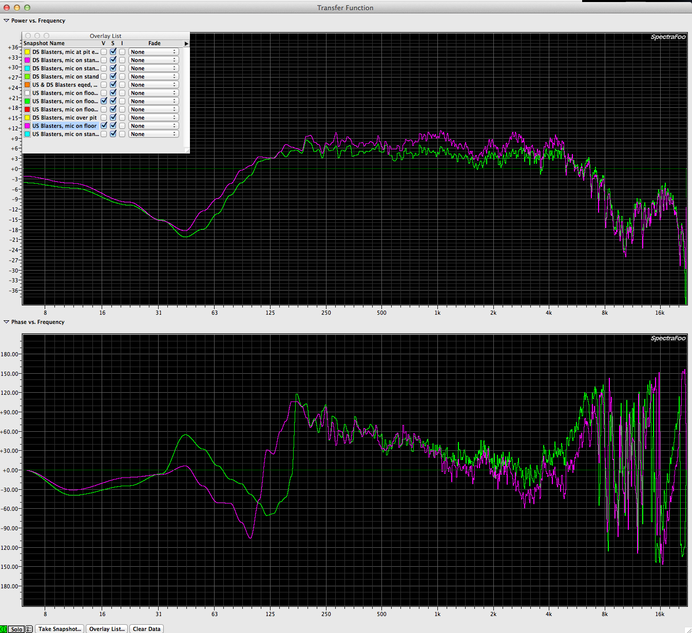
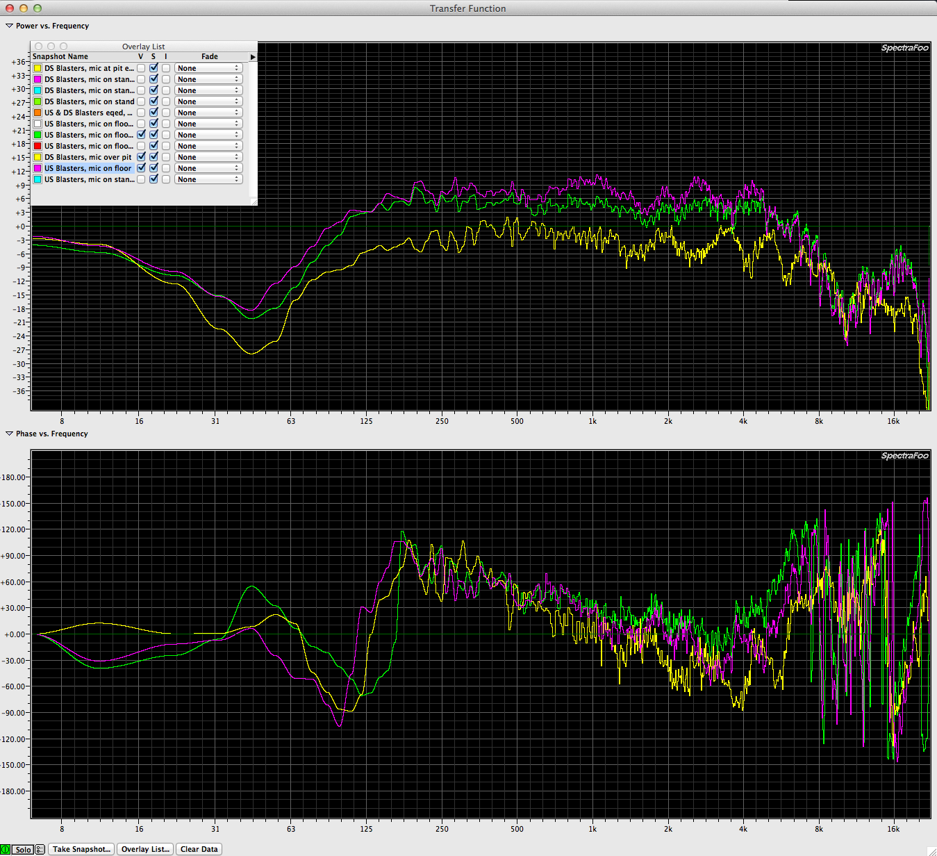
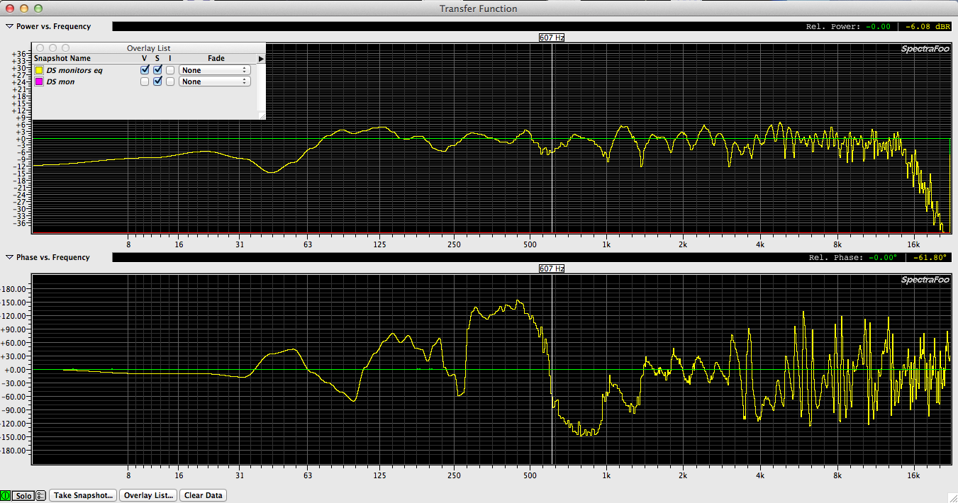
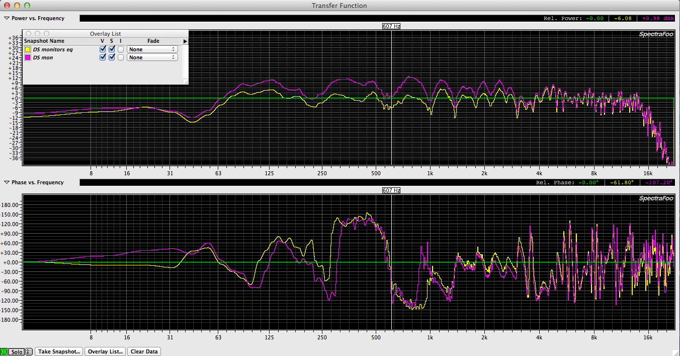
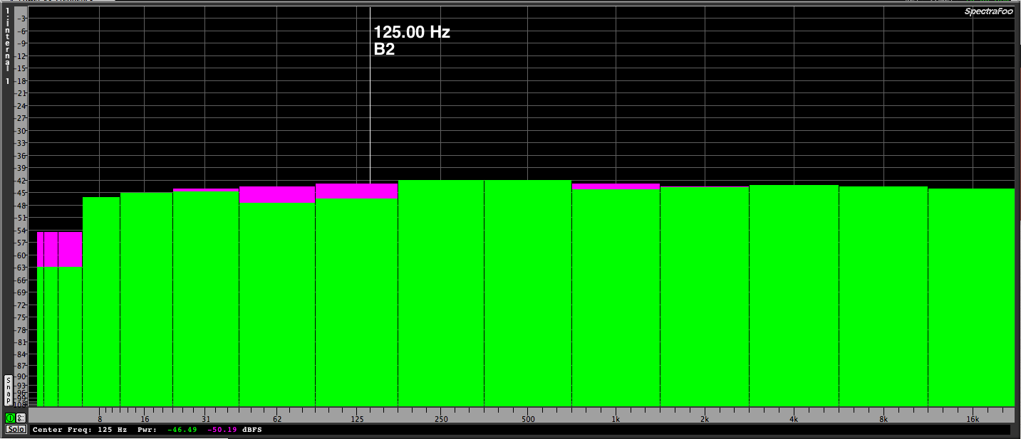 1 octave scale
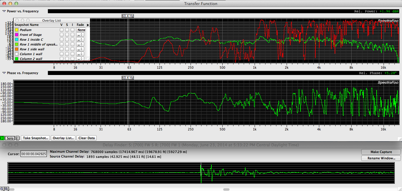
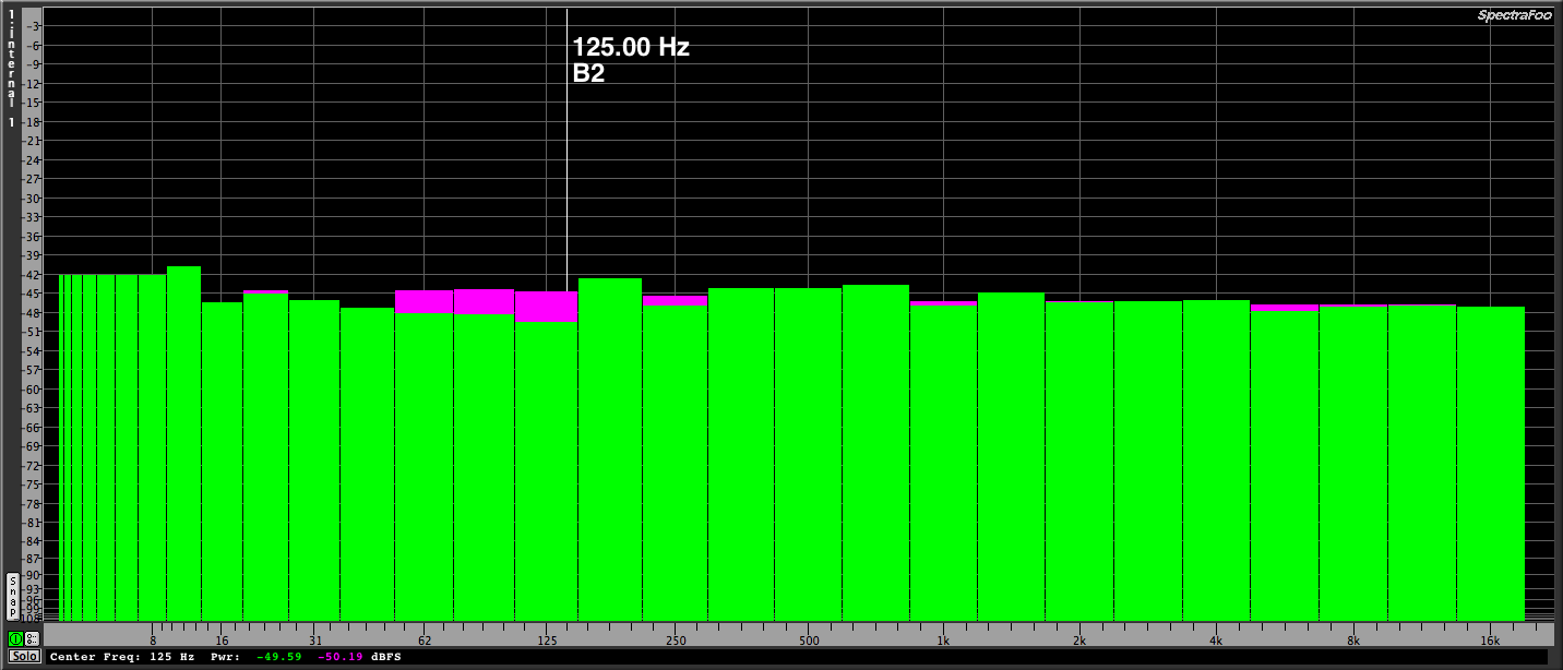 1/2 octave scale
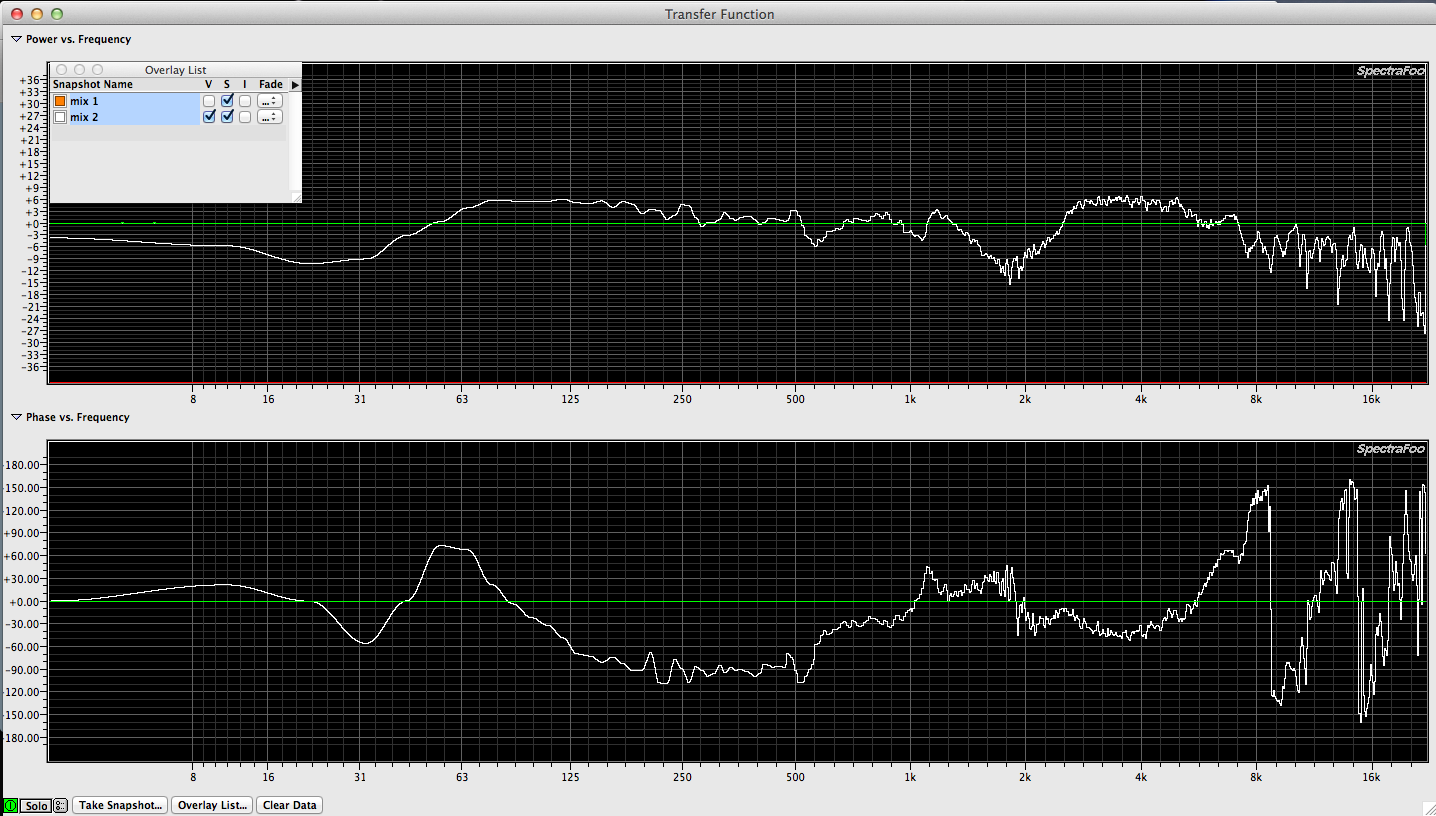
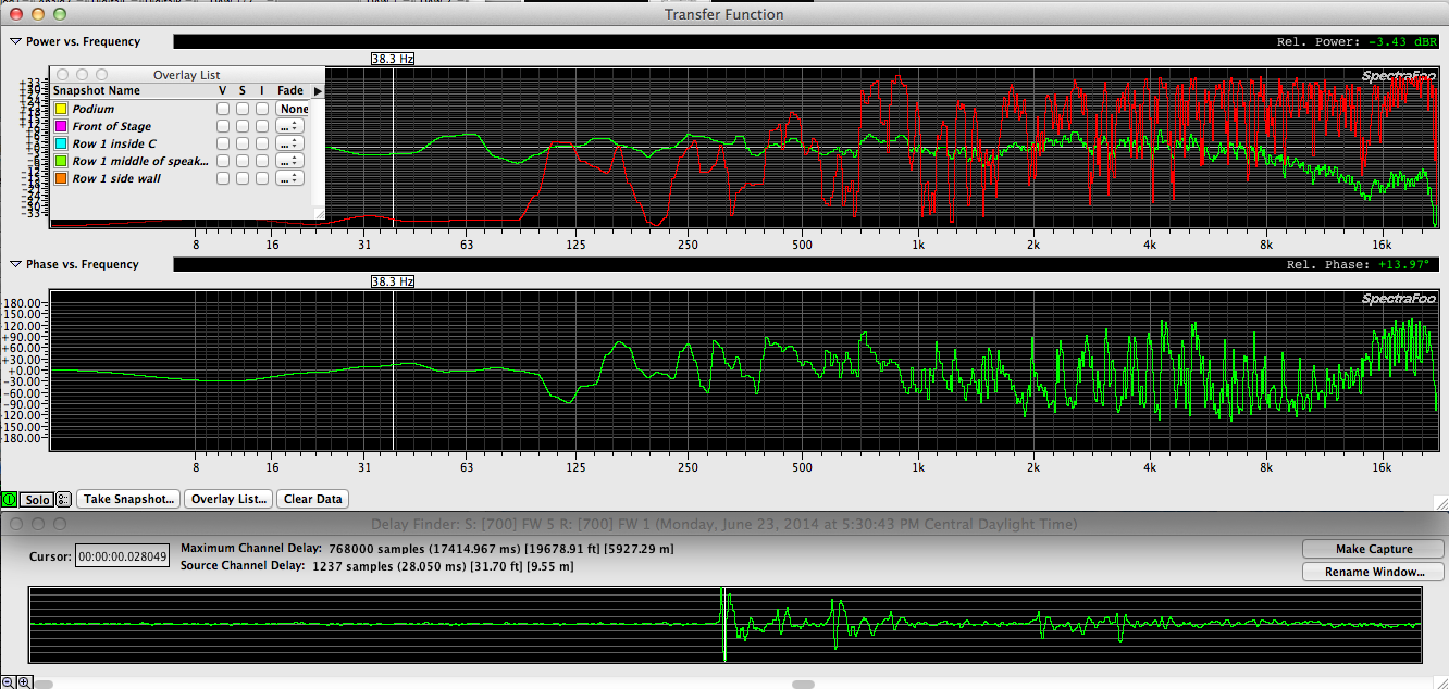
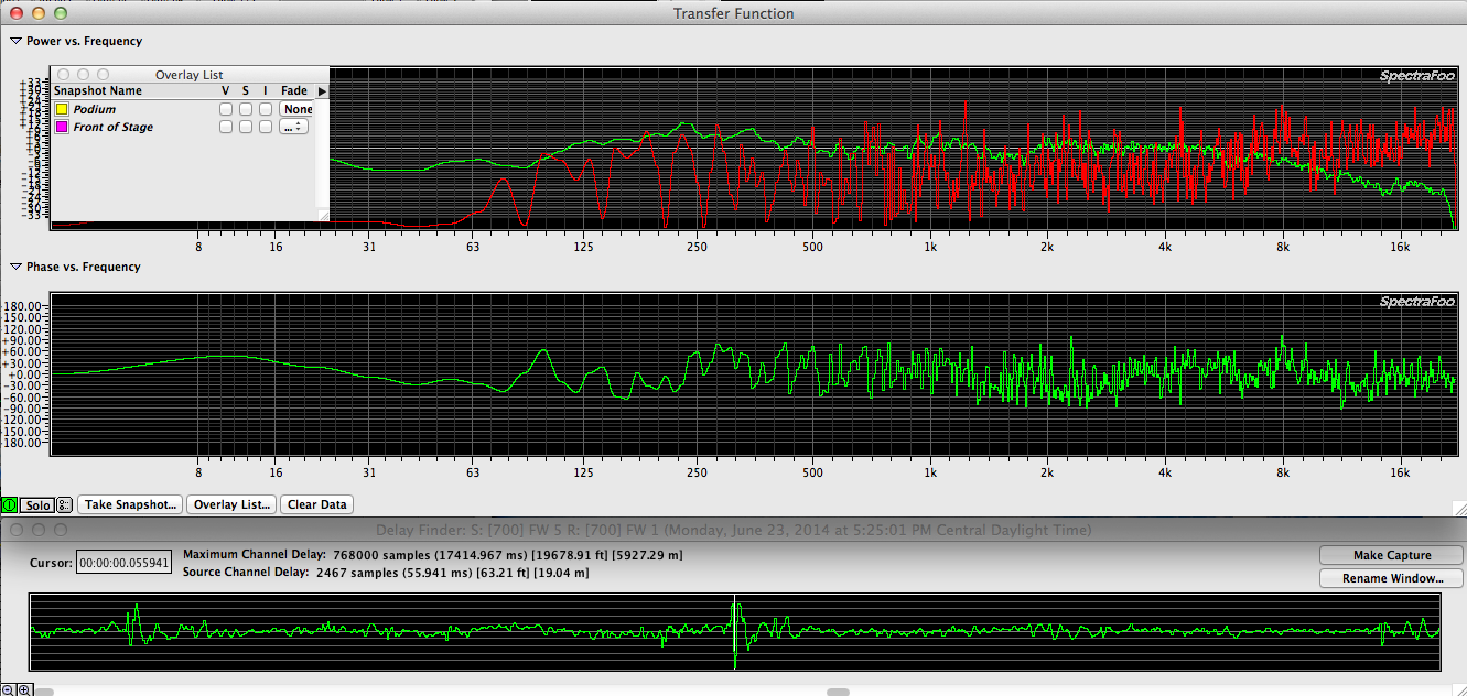
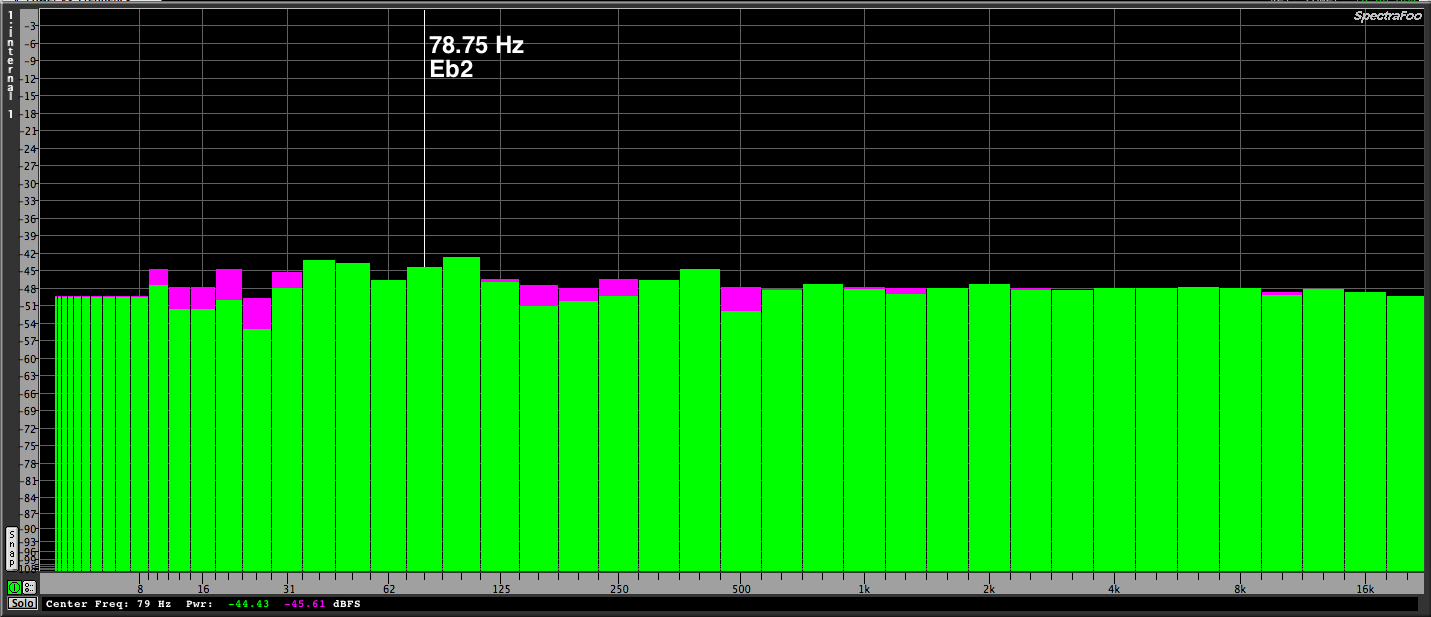 1/3 octave scale
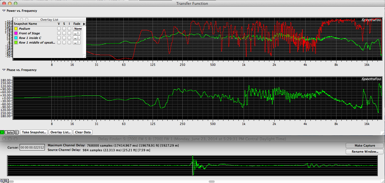
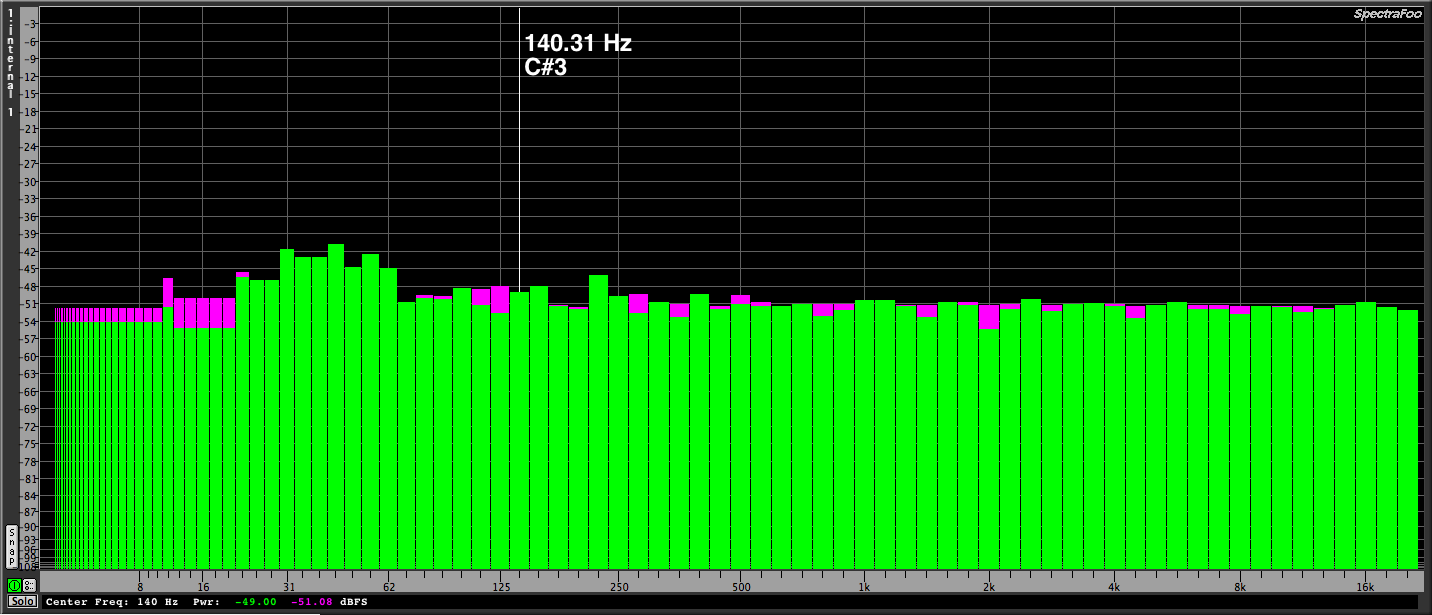 1/6 octave scale
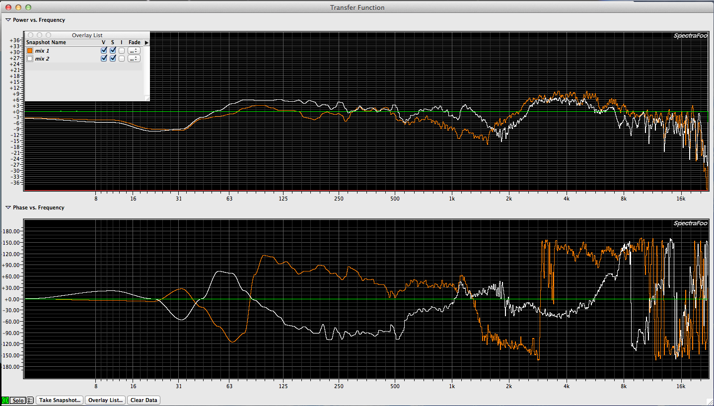
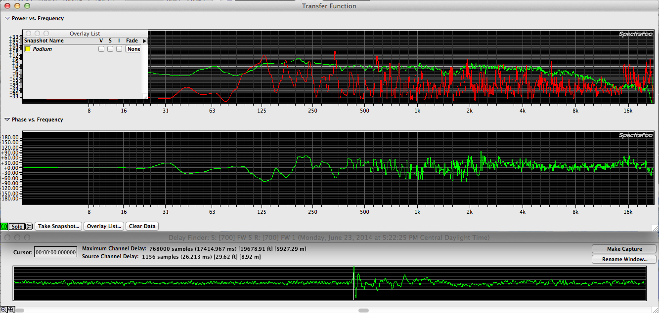
 1/12 octave scale
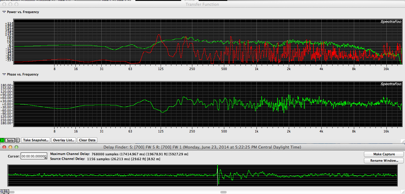
 1/24 octave scale
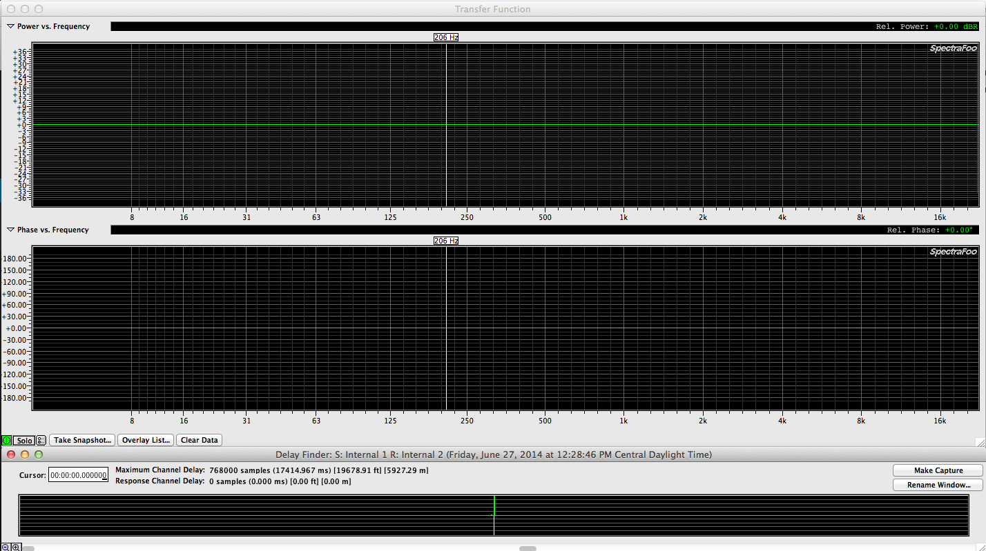