Meyer Sound SIM3 Remote
Having spent a day working with SIM3 and not knowing how to get my measurements off the machine so I can post the results, I checked with 606 who provided the following details via text.
”
Option 1) file: screen dump – makes a .bmp Then you have to burn a CD-R to get it out.
Option 2: SIM Viewer
Option 3 : run SIM on VNC viewer and screen grab from there
”
Choosing the path of least resistance, I choose option 3. How???
I wrote Meyer Sound tech support and this is the reply:
“Hello,
Here is some information that I have for SIM3 Remote. I’m not sure if the link to
download the .iso file will work for you or not. If it does not, let me know and I
will get it to you in another way.
Here is the final version of SIM3 Remote with a full time working vnc and sftp
server, with a working permanent installer.
This version will allow you to be Local and remote at the same time.
For training purposes this will allow to download SIM3 Remote Installer ISO
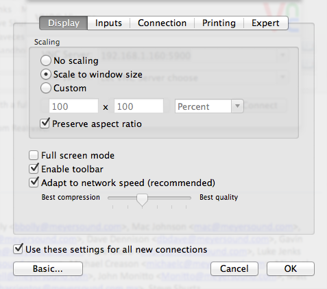
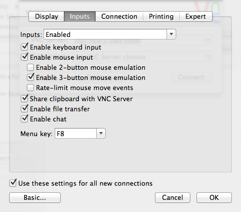
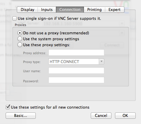
In order to connect to the remote SIM please use the VNC viewer from Real VNC.
Download VNC Viewer
Here are the VNC viewer configuration parameters…
You will need a keyboard, mouse and screen for permanent install… otherwise just put
in the CD into the SIM3 unit and wait for it to start booting from the CD. The
default IP address will be 192.168.1.160, but you can permanently install it to any
other IP address
You will, once the installer completes (you will see the command prompt), need to
reboot the machine and remove the CD.
If you have SIM3 remote installed to the SSD of your SIM3 machine when booting up
please just wait until booting completes and you will have both the local version
and multiple remote versions available.”
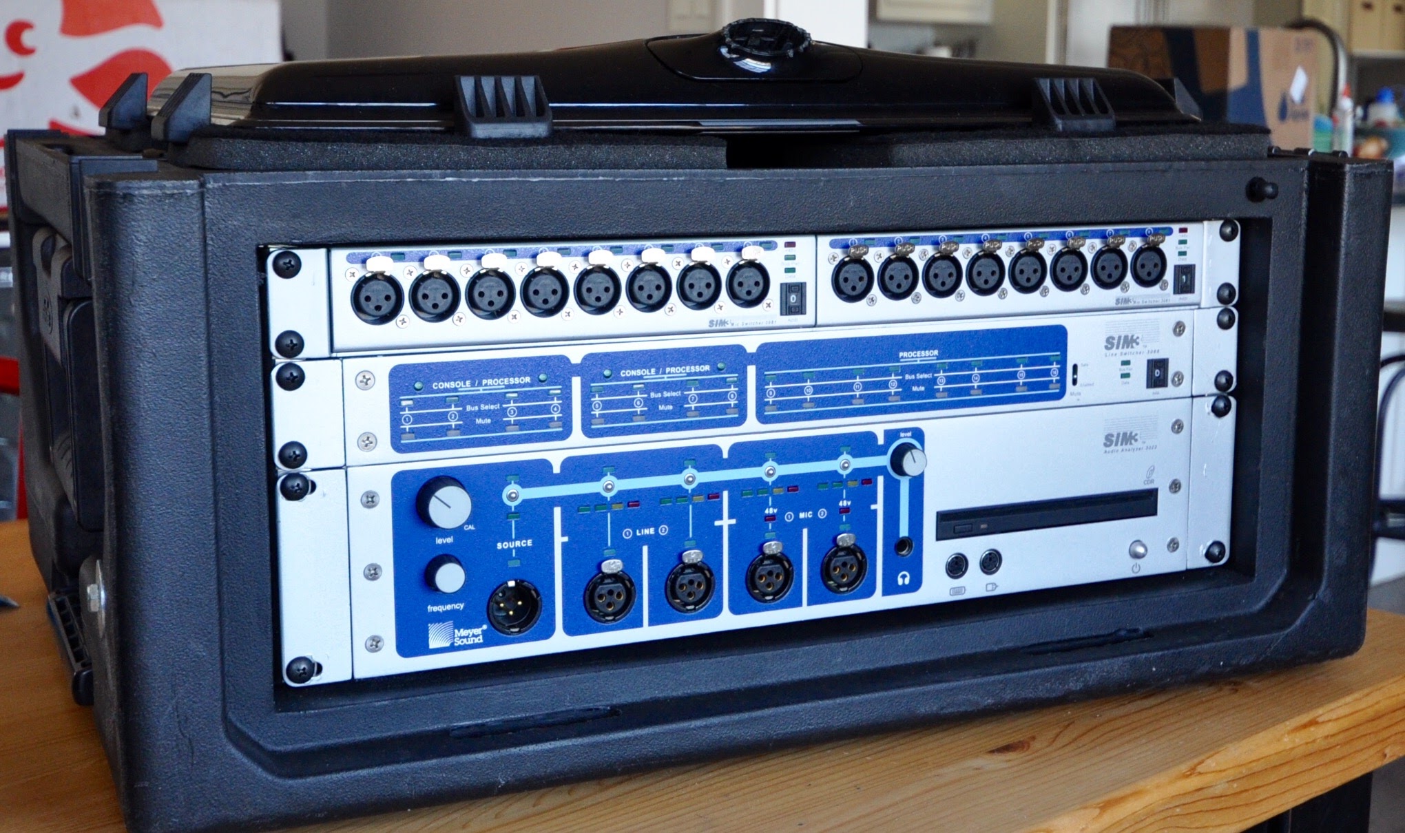
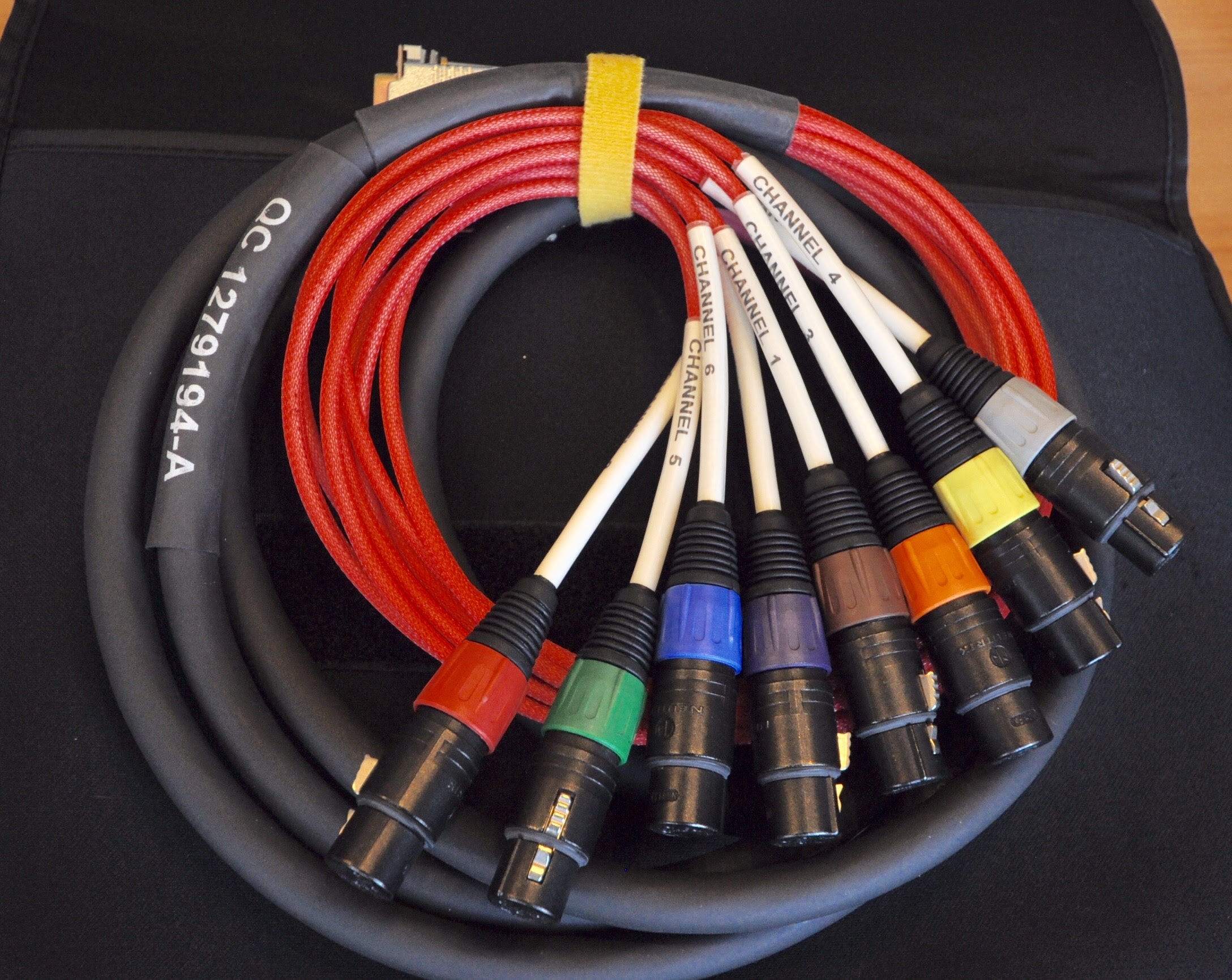
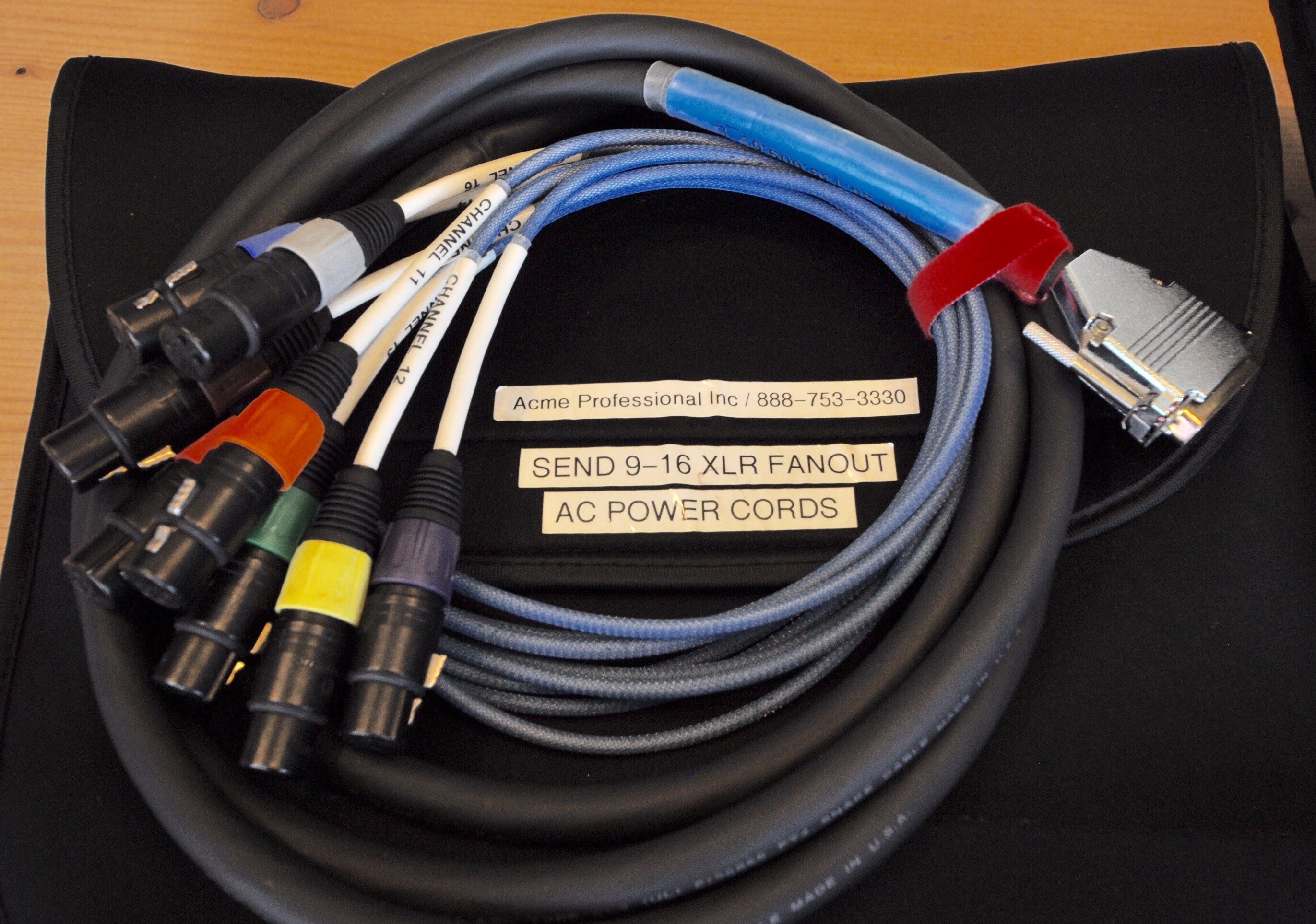
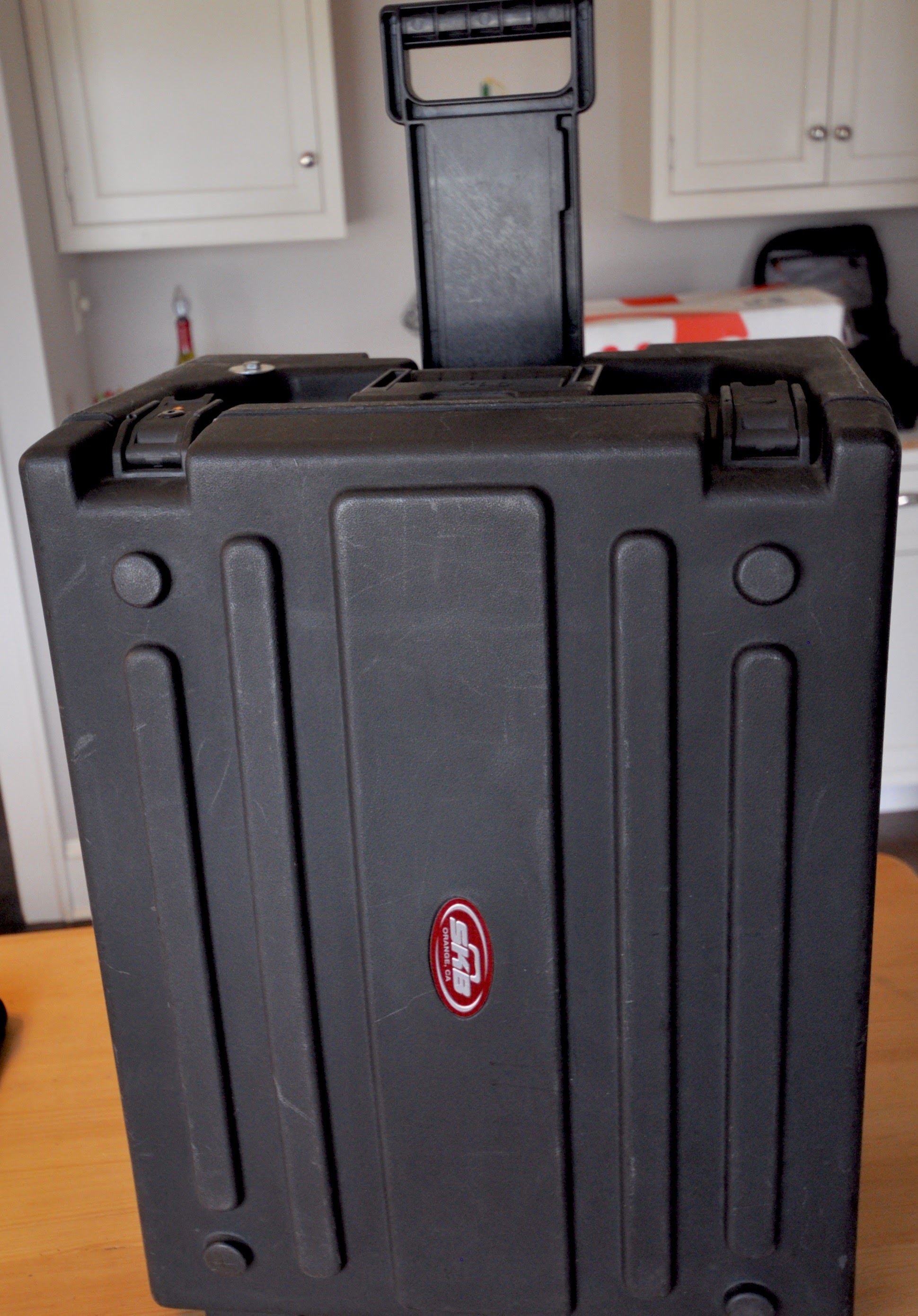
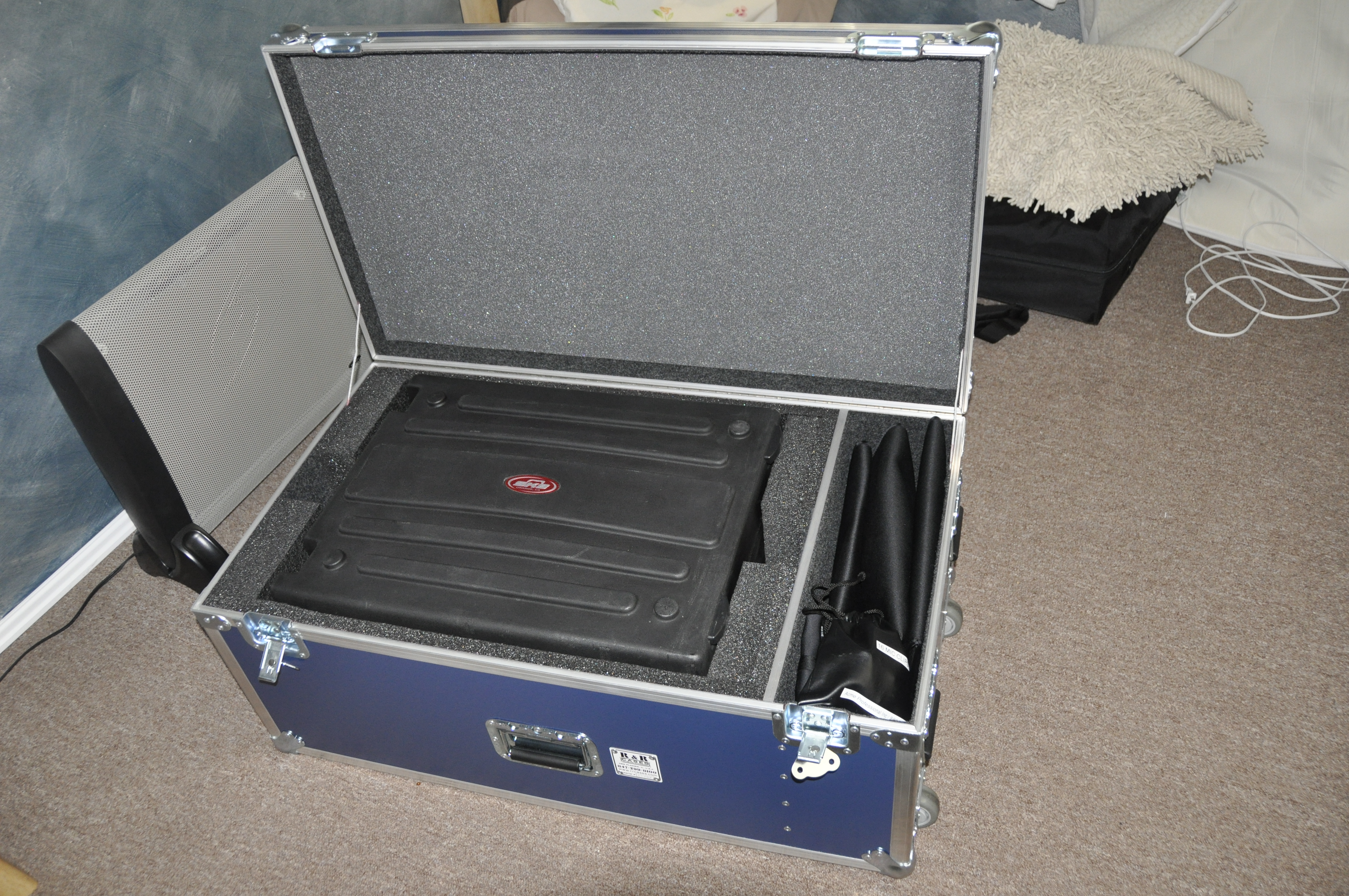
Acme Professional Inc – Meyer SIM3 / DPA rig for sale
To whom it may concern, Tom Clark of Acme Professionals has a Meyer Sound SIM3 3022 Audio Analyzer system for sale that includes (2) SIM-3081 Mic switchers and (1) SIM-3088 Line Switcher. The kit also includes multiple DPA 4091 measurement mics, misc cabling and road cases. Interested parties should contact Tom directly.

In case you’re not familiar with Acme Professional and Acme Partners,
acmesoundpartners.com – projects
acmeprofessional.com – projects


MATHEMATICS OF THE DISCRETE FOURIER TRANSFORM (DFT) WITH AUDIO APPLICATIONS SECOND EDITION
Temperature / Period “Time” / Frequency / Wave Length / Note ID
In my opinion, when it comes to a complicated system, more information is better than less information. This goes for a simple computer, car dashboard, airplane control panel and certainly a measurement rig. When you are presented with related data such as the outside temperature in Fahrenheit and Celsius you begin to learn how they relate to each other. Not true if you are using only one temperature scale. Since temperature affects sound, we should understand temperature scales.
Celsius = -17.7778 / Fahrenheit = 0
Celsius = 0 / Fahrenheit = 32 (freezing point of water)
Celsius = 37 / Fahrenheit = 98.6 (average temperature of a human)
Celsius = 37.778 / Fahrenheit = 100
Celsius = 100 / Fahrenheit = 212 (boiling point of water)
The Fahrenheit temperature scale seems to be more useful for discussing human environments as 0 degrees is pretty cold and 100 degrees is pretty hot.
Celsius is the perfect temperature scale to discuss different states of water. 0 to 100
But knowing both scales and how they relate to each other is obviously a superior approach than choosing only one or the other. The same is true for audio. It’s vital that we can think in period (time), frequency (Hz) and wave length (distance) if we’re going to see “the big picture” as it relates to the data a measurement rig provides. I’ll add onto that list of related values the note ID since most of us in the professional audio industry are working in music. If our measurement instrument can provide us with all of those at the same time, obviously the relationship between them all becomes much clearer over time. In that way we quickly learn that a 1k frequency is approximately 1.1 feet long. Then logic can fill in the blank that a 10k frequency is approximately .11 feet long and 100hz is 11.1 feet long. Going further, 500hz is 2.2 feet long, 50 Hz is 22 feet long & 5k is .22 feet long. Ad infinitum.
Once you recognize the relationship between a frequency, wave length and period, it’s much easier to recognize trends on your measurement rig and to anticipate how one decision will affect another. Audio measurement 101 is learning the tools and understanding what the instrument is telling you. Audio measurement 102 is about anticipating what the instrument should reveal and understanding what is going on if it doesn’t. As 6o6 stated in his class, he places his mics where he wants to see something, not the other way around. Meaning you put the mic where you want to measure and then aim the speaker at the mic. When the mic measurement shows the expected result, you’re properly aimed. Makes too much sense!
Here is a calculator for converting between decimal feet and fractions of feet.
daveosborne.com – decimal feet
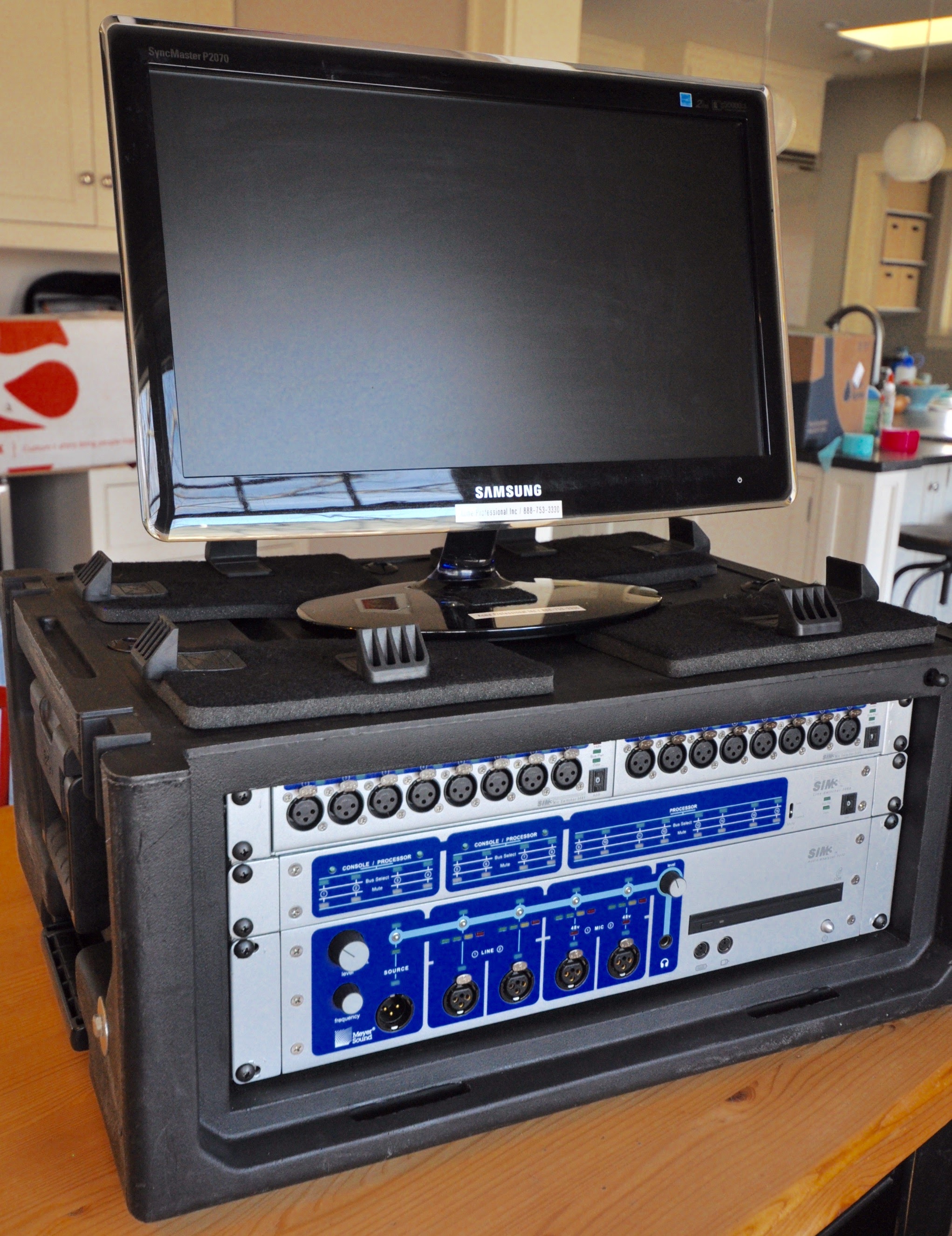
Dave Lawler’s SIM3 rig – day 2
Possessing a Meyer SIM3 rig is the first step to using a SIM3 rig but unlike a laptop / Smaart rig which gets used for lots of other things like email, Qlab programming, etc… SIM3 serves no other purpose other than measuring audio. Duh! I have been in possession of the rig now since Sunday and I still haven’t made a single measurement. Why? Because I have to find a place to set it up. This no fault of SIM3 but where as I can measure with my laptop while I’m getting other work done, SIM3 is going to require learning the interface, keeping it in one safe place, etc… Maybe this afternoon I can find that place and get it setup.
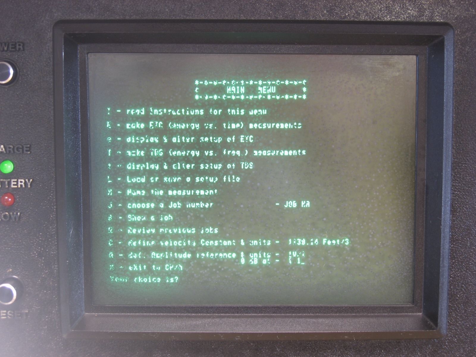
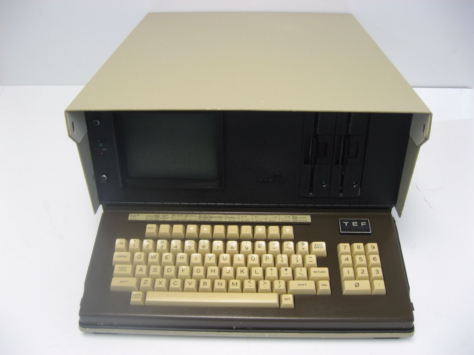
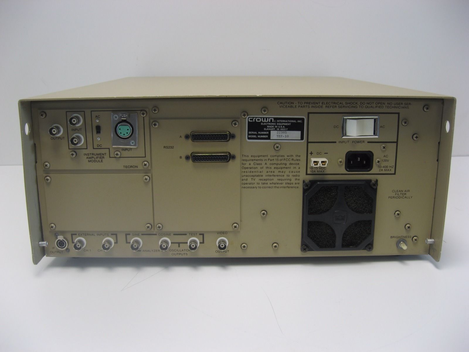
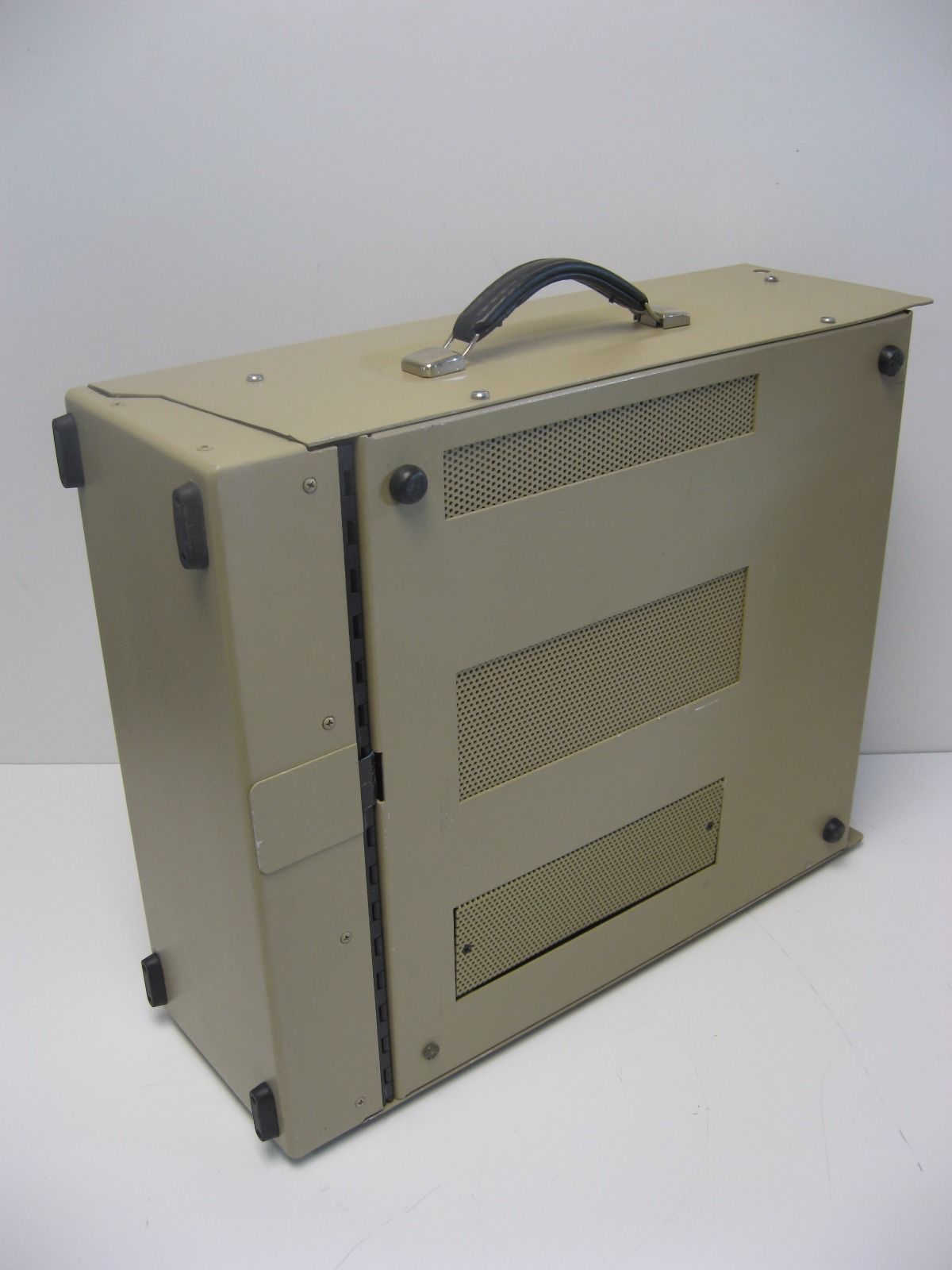
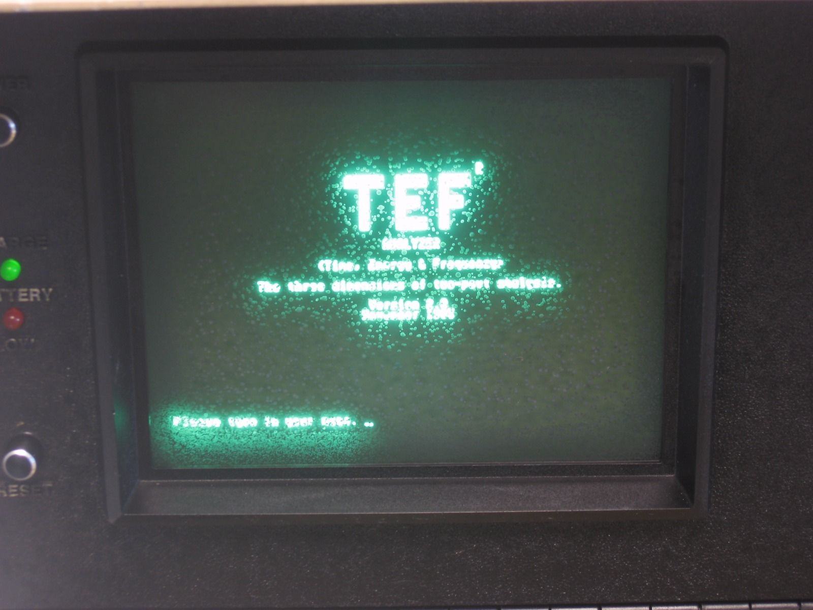
Crown TEF
I was reading a forum thread about an unnamed speaker manufacturer that still uses a TEF analyzer and thought I would read about the device.
Unfortunately I can’t find a wiki article on TEF but here is some basic information:
TEF stands for “Time / Energy / Frequency Analysis”.
“TEF is the invention of Richard C Heyser, TEF was brought out of Richard’s lab and into the world by Don Davis of Altec and our friends at Crown Audio.
Richards brilliance was brought into the audio world in 1967? when a paper submitted by him on a new (his) audio measurement method was discovered in a trash can of the AES by none other than Harry F Olsen.”
It just so happens that there is one for sale on eBay right now which provides an opportunity to see what one looks like.

The only modern TEF system I can find is produced by Gold Line:
gold-line.com TEF webpage
Dave Lawler’s SIM3 rig – day 1
I was talking with Dave Lawler the other evening via telephone about my interest in spending some time with a Meyer SIM3 measurement rig and it just so happens that his SIM3 rig was left at Winspear Opera House in anticipation of his next visit to the venue. Dave is graciously loaning it to me for the moment and I collected it this evening from the venue and took it back to the shop to set it up and make sure it works with the VGA monitor I have. It does! Until Dave asks for it back, I’m going to learn everything I can about SIM3.
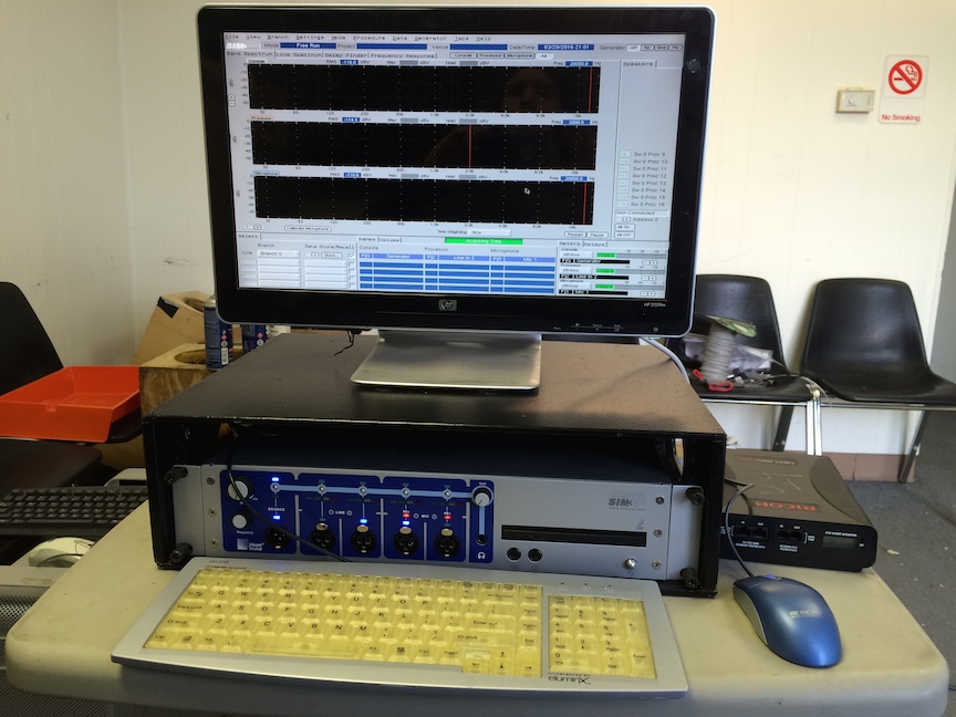
Now if I only knew what to do with it…
Here is the SIM3 documents page on the Meyer Sound website:
Meyer Sound – SIM3 documents
One of the things that I want to figure out is how to take screen shots of the data provided by SIM3 so I can share it here. Do you know how? Contact me…
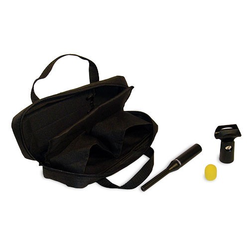
Rational Acoustics RTA420 mic with calibration file
If you can’t afford a high quality measurement mic (meaning a mic with a flat frequency response), an inexpensive path to getting something you can trust for Smaart use is Rational Acoustics RTA420 mic.
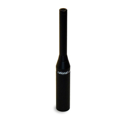
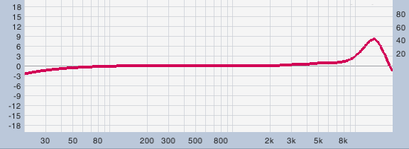
An RTA-420 mic does not have a flat response but if purchased with the calibration file option, Smaart allows the user to load the calibration file into the app so that the frequency response of the mic is corrected.
This is a link to the RTA-420 mic without calibration file:
RTA – 420 measurement mic
This is a link to the RTA-420 mic with calibration file which has been serialized, measured in a lab to provide the file.
RTA – 420 measurement mic with calibration files
If you’re going to purchase an RTA-420, definitely pay a little extra and get the version with a calibration file.
I will post more details about the calibration process and show the with and without calibration file loaded results.
More soon.
What’s New in Smaart v8 – youtube video
Phase Align Parallel Sources Using Rational Acoustics SMAART
Smaart 8 – Everything you may want to know
The release of Rational Acoustics Smaart 8 is a major event in the audio measurement world. I upgraded my V7 license a few days ago and already prefer V8. So what is different?
rationalacoustics.com – V8 New Features Overview PDF
What does it cost to upgrade from older versions of Smaart?
rationalacoustics.com – V8 Pricing
How about the Smaart 8 user guide or licensing guide?
rationalacoustics.com – V8 Documentation
V8 facts:
rationalacoustics.com – V8 FAQ
Bandwidth in Octaves Versus Q in Bandpass Filters
In order to correctly set complimentary eq curves for speakers you need to be able to find the appropriate frequency center and then adjust the bandwidth.
Bandwidth is adjusted in two formats depending on who is providing the EQ. Octave and Q. These two terms are related but not the same. In order to use them you should understand their relationship.
WIKI – Bandwidth
WIKI – Q factor
Here is a Rane article written by Dennis Bohn on the matter:
rane.com – Bandwidth in Octaves Versus Q in Bandpass Filters
Here is the PDF version of the same article:
rane.com – Bandwidth in Octaves Versus Q in Bandpass Filters PDF
Here is a spreadsheet that coverts from one format to the other:
rane.com – Bandwidth vs. Q Calculator
How to set up Smaart to act like SIM3
A fellow system engineer and mentor of mine uses SIM3 exclusively for measurement purposes and prior to that he used SIM2. It just so happens that his SIM3 rig is in town after a previous measurement / tuning session and he’s arranged for me to borrow it until it is needed on the next job. So soon I will have a SIM3 rig sitting in front of me side by side with Smaart 8.
Who would know better than Jamie Anderson at Rational Acoustics how to configure Smaart to function like SIM3? So I asked the question and here is his response:
“I would set up an eq driving a speaker.
Grab three measurement points. EQ in, EQ out and the measurement mic.
Set up three TF’s:
Room, EQ and Result where:
Room = EQ out vs. Mic
EQ = EQ in vs. EQ out
Result = EQ in vs Mic
Set averaging to 3sec
Set averaging of EQ to 4 FIFO
Set EQ to graph inverted
show plot view as Mag/Mag (view #5)
Display Room and EQ TF’s in upper plot (plot 1)
Display Result TF in lower plot (#2)
That will give a standard SIM view.”
Next week I’ll have a chance to do exactly this and see how it works out. More soon.
Trinity Episcopal Church – parish sound system
I recently began the process of relocating (2) QSC K8 speakers in Trinity Episcopal Church’s parish hall to cover the room on a different axis.
QSC – K8
What was previous a L/R rig facing West will be a mono main / mono delay rig facing North.
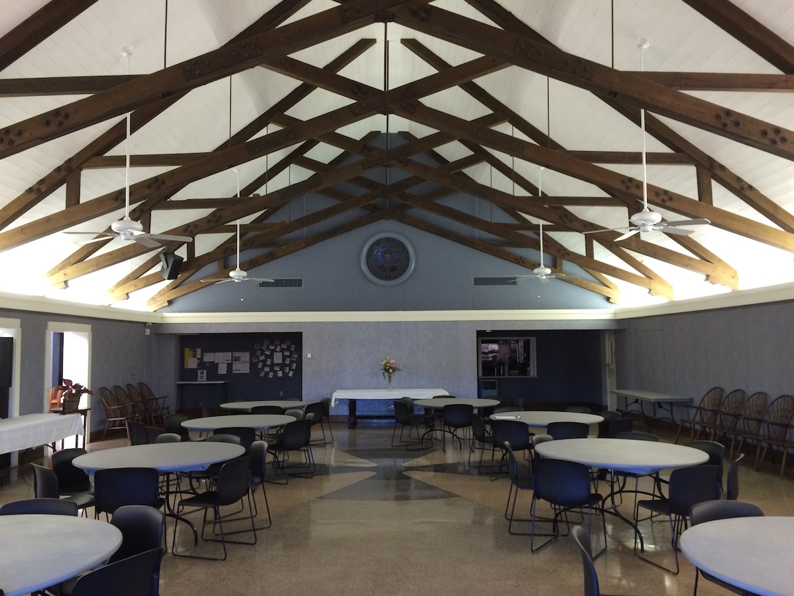
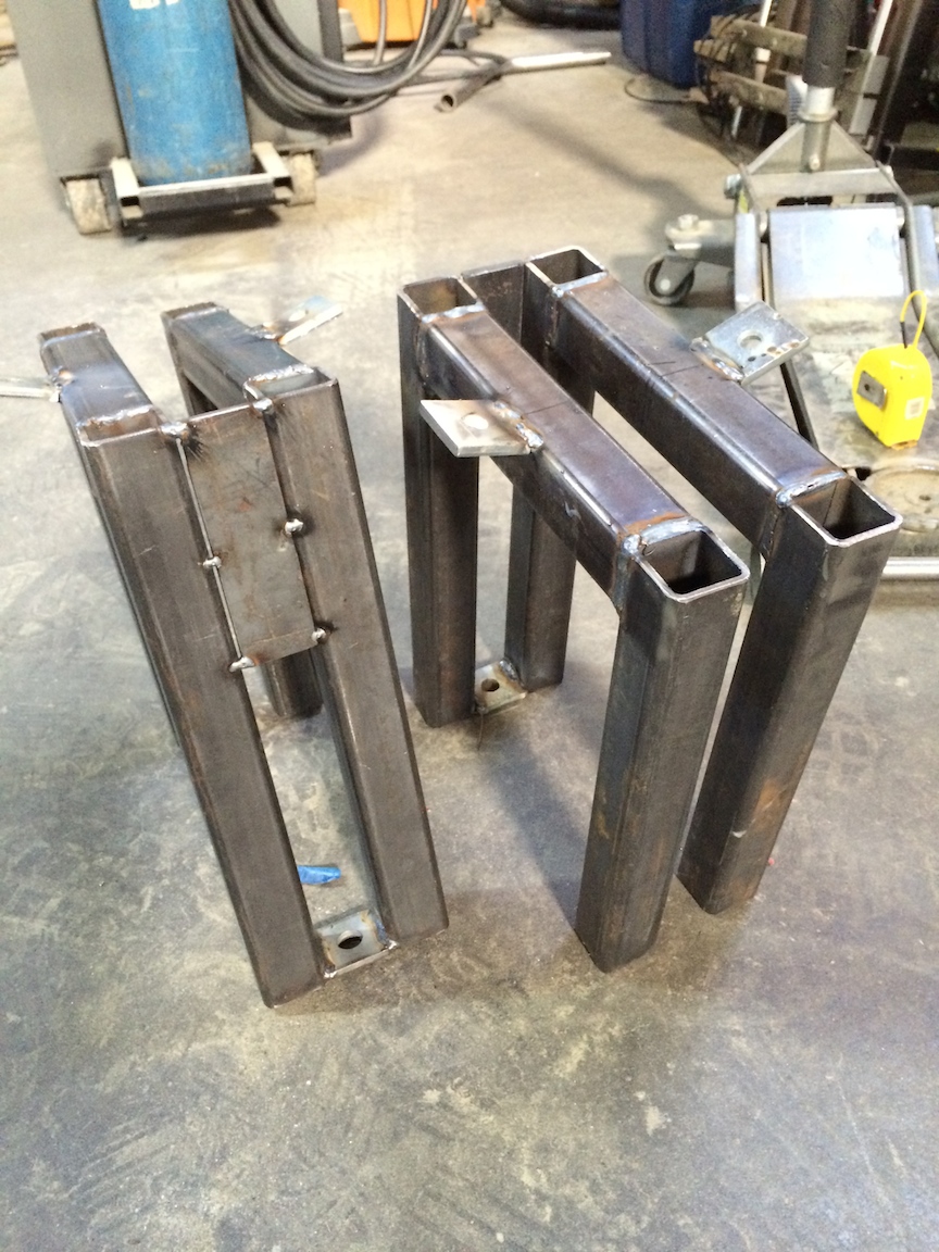
Custom mounting brackets were required to mate with the existing structure. Special thanks to True @ Toby Speakers for welding them together for me.
tobyspeakers.com

The “delay” speaker will be delayed to time align with the main speaker.
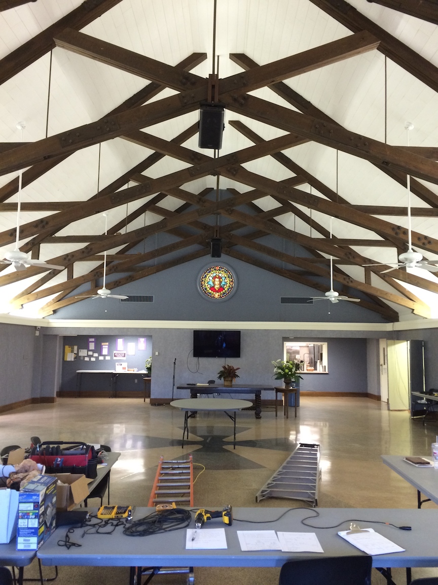
After finishing the wiring install and landing everything on the Yamaha 0/1V mixer, it was time to EQ the system and then set the delay time for the delay speaker. As is typical, the system without any EQ was excessive in the low mid frequency range. Here is what the single main speaker measured like on axis.
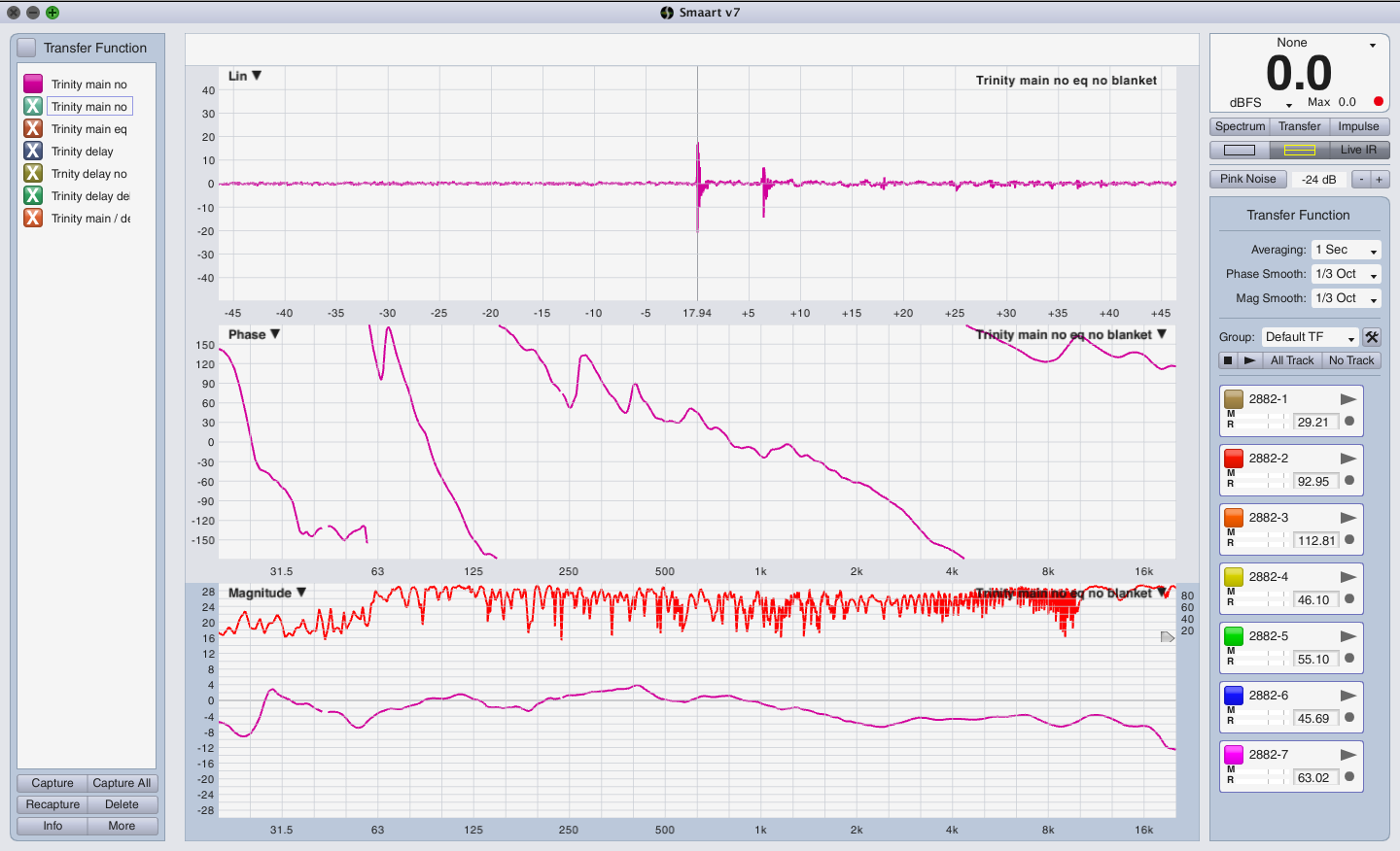 You will notice that there is a strong reflection which is due to the table in between the speaker and the mic. So I went and found a blanket and threw it over the table. This is the measurement now. Notice how coherence has greatly improved and the frequency response has changed.
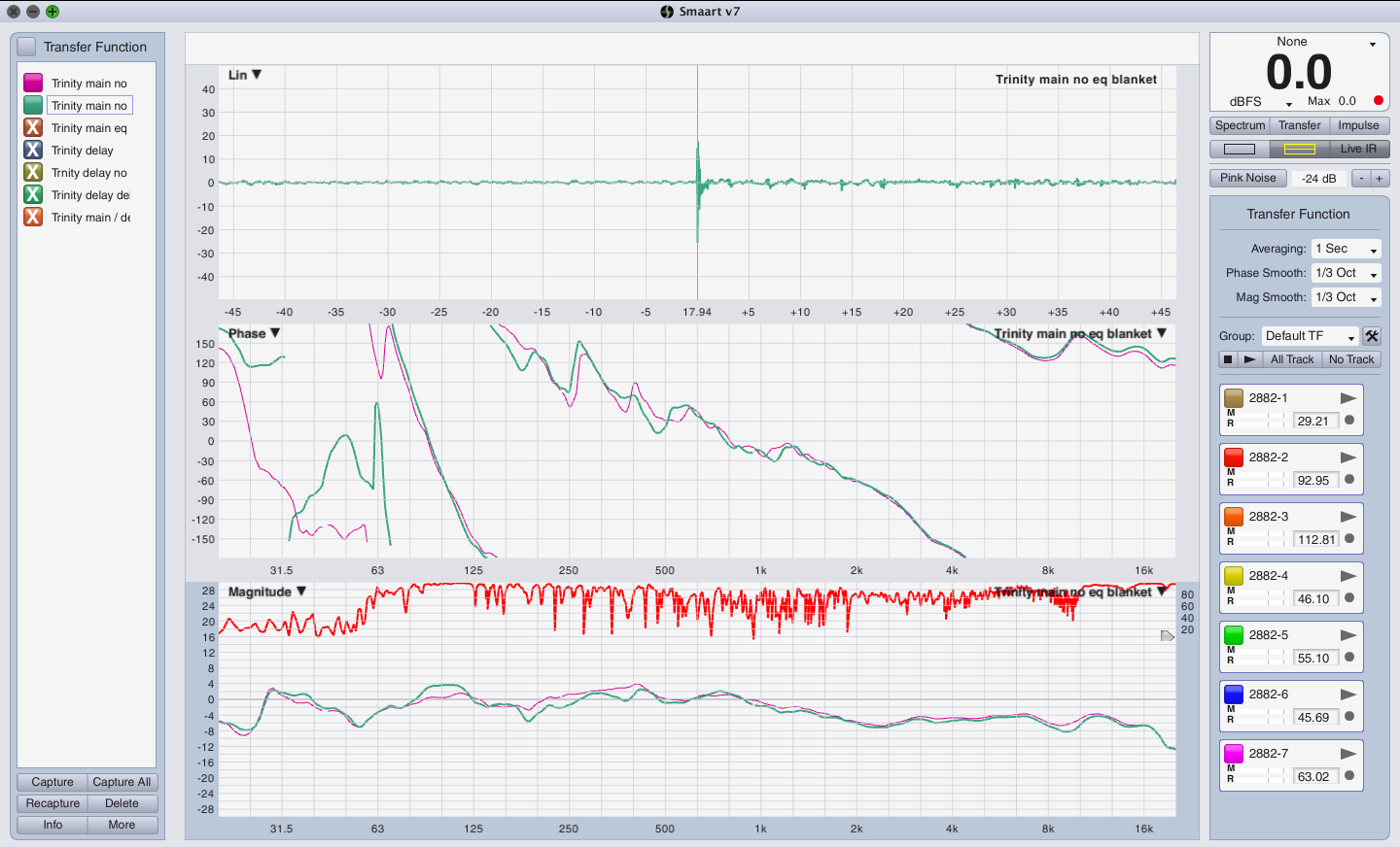
This is the response of just the main speaker pre and post EQ. 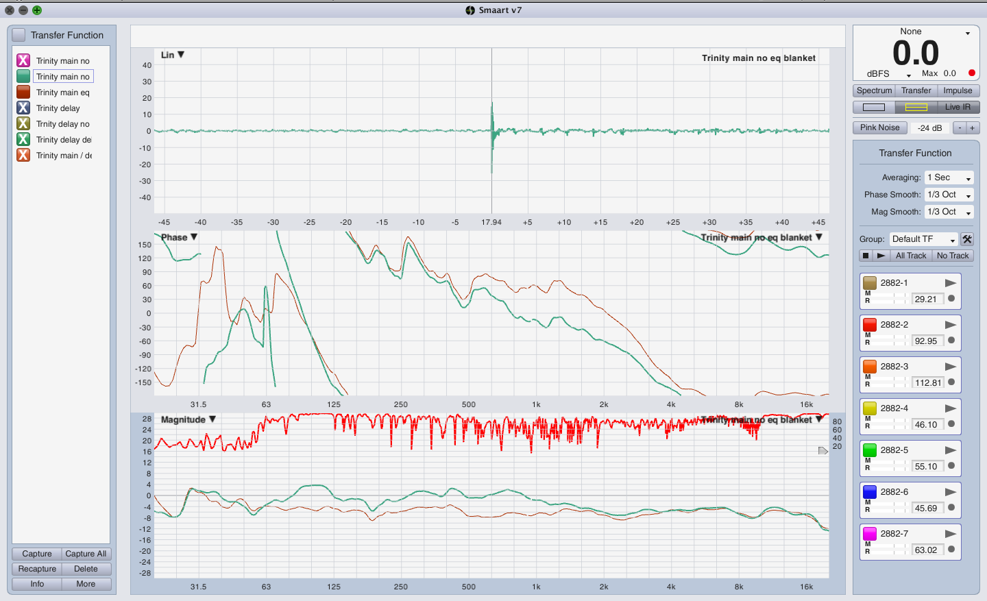 I’m using the stereo L/R to feed the two speakers so there is no way of having an eq setting for the L output and a different eq setting for the R output. The speakers match and are in roughly the same acoustic space. Hopefully they will work well with the same EQ. Here are the two measurements.
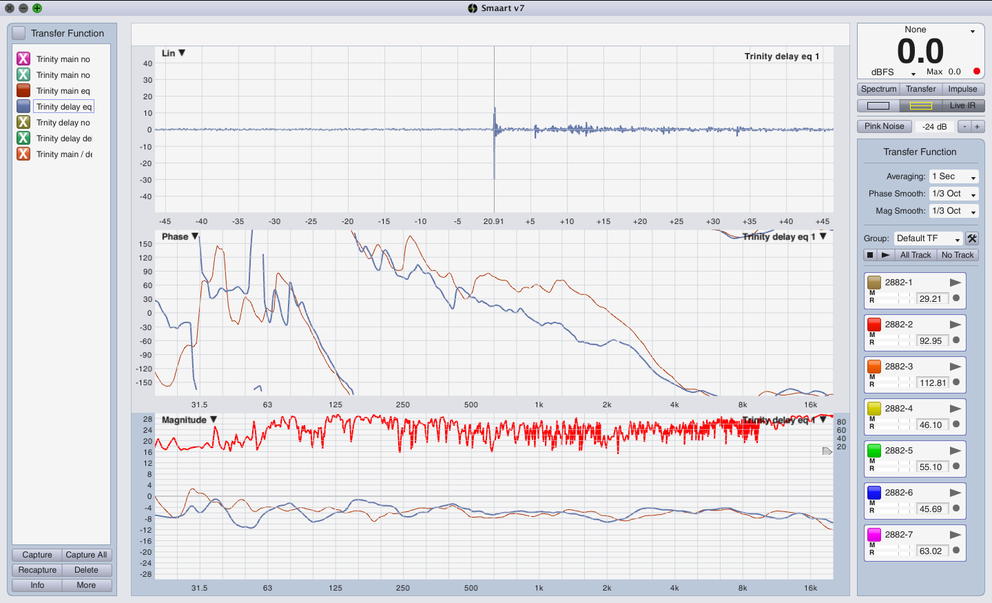 Next was to measure the main speaker at the transition zone between the main speaker and the delay speaker to get a base delay time. Then to measure the delay speaker to get that delay time. Obviously in this situation the delay speaker is going to be closer to the mic than the main speaker and so the delay speaker will need to be delayed. In this case the delay time turned out to be 16.1 ms, the difference between the main and delay speaker due to location. If the main / delay speakers are arriving early in comparison to the typical presenter location, we will delay both speakers back to the TV on the wall which will also help the imaging when a person is speaking into a microphone.
Arthur Skudra – how to setup a measurement rig using (2) Roland Octa-Capture
Trust me, measuring with multiple mics is addictive. Once you’ve used more than one mic for measurement purposes you immediately understand why having multiple mics is so helpful and saves a lot of time. On my last measurement process I used (7) mics which made it obvious that having even more is better. 6o6 has suggested to me that a 16 mic measurement rig is ideal.
How does one build a 16 mic measurement rig? For starters you need an audio interface with 16 mic inputs which is a rare bird. You can build one from 8×8 devices that include ADAT i/o but one must remember that there is a bit of latency involved any time you use a digital connection between boxes. As long as you stay on top of that, there is no reason it shouldn’t work. The more I measure the more I realize that “acceptable” and “ideal” are far apart and ignoring budget restraints, “ideal” is the target. Why? Time. In the world of professional audio where there are a chance for a loss of ticket sales or corporate accounts, time is money. If you can’t get the system up and running in the time you have, get faster! The element where I see speed greatly achieved regards RF based measurement. There other element is multiple mics. Put the two together and I think we have achieved an “ideal”.
One system engineer I know is doing just such things. Arthur Skudra has been invaluable in my pursuit of these two audio measurement elements (multiple RF mics) so it is not surprising that he has gone out of his way to make sure others have access to the same information he has learned.
This Rational Acoustics forum thread reveals how to take (2) Roland Octa-Capture audio interfaces and build a 16 channel measurement rig.
rationalacoustics.com forum – Why just settle for ONE Octacapture
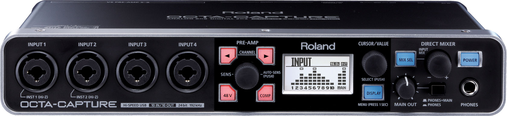
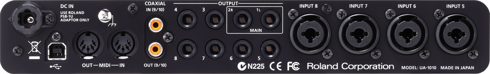
http://www.rolandus.com/products/octa-capture/
One of the things Arthur shares in this forum post is how he measures impedance of each speaker using a Dayton Audio DATS rig.
http://www.daytonaudio.com – DATS audio test system
A follow up with Arthur reveals that he’s now using a NTI MR-Pro for impedance measurement purposes.
ntiaudio.com – Minirator MR-PRO
Note that you also need the 70v/100v protective adapter kit to perform impedance tests.
ntiaudio.com – MR-Pro 70v/100v protective adapter PDF
Sam I Am – Sam Berkow in profile
THD
WIKI – Total Harmonic Distortion / THD
ap.com – THD+N
tungsol.com – Why is there a difference in Tube and Transistor sound
In the heyday of tubes and transformers, a certain amount of distortion may of been desirable but certainly not in the modern day of digital mixing consoles and digital signal processors. Unlike analog tape and analog circuits, most digital audio is a stream of 0s and 1s (binary). There is nothing to be gained by clipping one or more of these devices in a signal chain but ugliness.
Case in point. Recently while performing some electronic measurements on a Soundcraft Vi6, I tested the threshold of clipping going in and out of the console to learned whether or not the red light on the input / outputs comes on at the same time or not.
Eisemann Center – Hill Performance Hall
Why mics are used to enhance a pit orchestra for the stage and audience
There are two good reasons to mic the instruments in a pit. For one, anytime there is a need for putting the musicians in a pit there is obviously something on stage. It could be a broadway musical, ballet, opera, etc…
Some “purists” would suggest that there is no reason to mic the instruments in the pit but they would be misinformed.
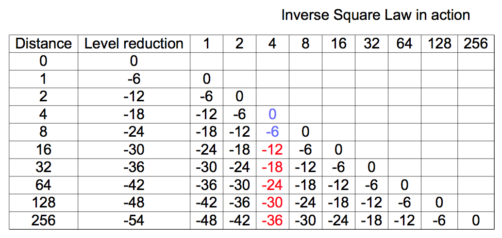
Unlike an orchestra shell / reflector setup that is designed and used to enhance the acoustic instruments on stage, a pit is neither. A pit is a compromise of space versus audience seating. A pit is neither acoustically similar to an orchestra shell but is in some ways a worst case scenario. For anyone but the front few rows, there is no direct sound to be had from the pit because of the pit rail and the stage extending out of the pit. There is a window of direct sound to be had but it’s not available until you get up into the balconies. What this means is that a patron seated on the orchestra level (other than the first few rows) are hearing reflected sound only. None of which is imaging sonically to the pit. Instead the reflections may be coming from the ceiling which may be as far away as 100 feet. A round trip up and down again could be 200ms (a 1/5 of the second) and suffer significant air loss along it’s journey. In sound design terms this situation would be completely unacceptable but for the “purist”, that is acceptable and preferred. Ignoring the matter of reflected sound versus direct sound (what the front rows get), there is the matter of the inverse square law which states that the sound level drops by 1/2 with each doubling of the distance from the sound source. Ignoring boundary effects, what this means is that in a typical concert hall, what may be acceptable as a sound level near the pit is completely unacceptable in the upper balconies. Industry standard for level variance is =6db. This means that in general, every seat should be covered in such a way to have a variance of -6db. If the front row is our 0db reference (closest to pit), the furthest seat in a venue should be no less than -6db (1/2). Acoustically and physically, this is impossible but easily accomplished with a well designed sound system. For reference, I recently worked in a venue that measures roughly 150 feet to the furthest seat from the stage. What sort of level could one expect to experience siting in that seat if there is only acoustic sound coming from the pit? Let’s assume that the person sitting on the front row in the very center of the venue is 4′ from the conductor & first violin. What they are hearing is our 0db reference. Looking at the following chart, as we travel 16′, 32′,64′,128′, etc… we quickly move out of the “acceptable” realm of sound system design. The -6db window. By the time we get to the far upper balcony, the level has been reduced by at least 30db.
In any sound system design, there would be speakers that are involved to provide coverage in the furthest seats. In the case of an all acoustic pit orchestra, those sitting in the furthest will have a completely different experience than those who purchased seats near the pit. I have recently heard the argument that people should get good seats early and those that get poor seats can just suffer. I agree with this concept IF the seating is defined as good and poor and everyone is told in advance of purchase that some seats are inferior to others, anyone who chooses a poor seat shouldn’t expect the same experience as someone who paid more and has a good seat. We all know this is NOT how things work. Instead there are expensive seats and less expensive seats but no one expects to be unable to hear just because they have a less expensive seat. Consequently, it’s the job of the venue / sound system designer / production sound designer to make every attempt to make sure that every seat in the venue fits within the previously stated goal of a 6db window of variation.
In an acoustic space, not only is there the matter of a loss of level per doubling of the distance but also air loss which reduces high frequencies and then boundary effects which enhance low frequencies but don’t help the lost high frequencies. “Muddy” is an appropriate term for what to expect in the far seats of a concert hall when listening to an orchestra in a pit without some sort of “enhancement”.
In summary, there are (3) concepts that should be considered regarding whether there is a need for enhancing an acoustic event.
1. Loss of level due to distance
WIKI – Inverse Square Law
sengpielaudio.com – square law calculator
hyperphysics.phy-astr.gus.edu – inverse square law
hyperphysics.phy-astr.gus.edu – Estimating Sound Levels With The Inverse Square Law
acousticalsurfaces.com – Inverse Square Law
2. Air loss due to distance
sengpielaudio.com – sound distance calculator
3. Boundary Effect – explanations
SYN AUD CON – How Boundaries Affect Loudspeakers – article
SYN AUD CON – How Boundaries Affect Loudspeakers PDF
Sound On Sound – All About The Boundary Effect
argen.com – Is Speaker Boundary Interference Killing Your Bass?
audiomasterclass.com – How A Boundary Mic Gives Crystal Clear Sound
A rule of thumb regarding loss from distance is that 10x the distance will result in a loss of 20db. If 4 feet is your 0db reference point, 40 feet will be -20db.
Meyer UP Junior / 650p sub PA
A fellow audio engineer invited me to help him put together a small PA for a special event on stage.
Rational Acoustics Smaart 8 pricing
Rational Acoustics just released pricing and upgrade information for Smaart 8 which will be released on March 15th, 2016.
Rational Acoustics Smaart 8 details
Rational Acoustics Smaart 8 pricing