Phase explained
Frequency Response explained
Impulse Response explained
Earthworks Electronic Calibration File – webpage
Omni Mic Application Guide
The World Beyond 20khz – David Blackmer white paper
How Earthworks measures mics
This PDF makes for an interesting read.
Earthworks – KP1 “Kickpad”
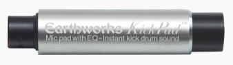
Earthworks Audio website – Kickpad link
Here is the description from the website:
“Just Plug the KickPad™ into the mic line feeding your favorite cardioid kick drum mic and you will experience an incredible instant kick drum sound that is exactly repeatable, every time. The KickPad™ can also be used for vocals and bass. This will work with any device that has a 3-pin XLR. The KickPad™ is a passive device (requiring no Phantom Power) that can be used with either condenser or dynamic microphones. It works for both recording and live performance applications.”
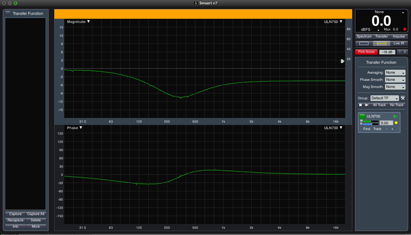
What does it do really???
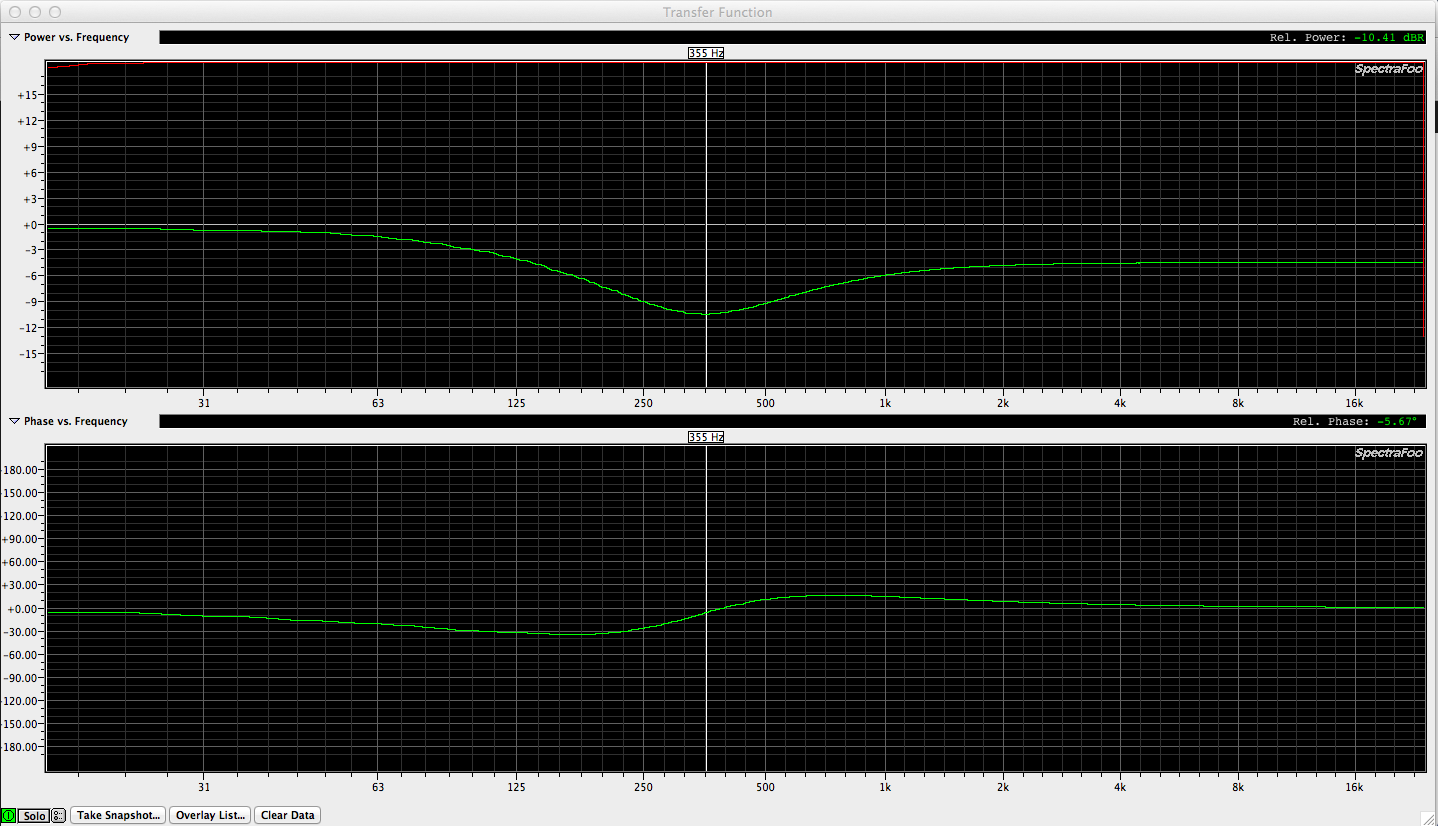
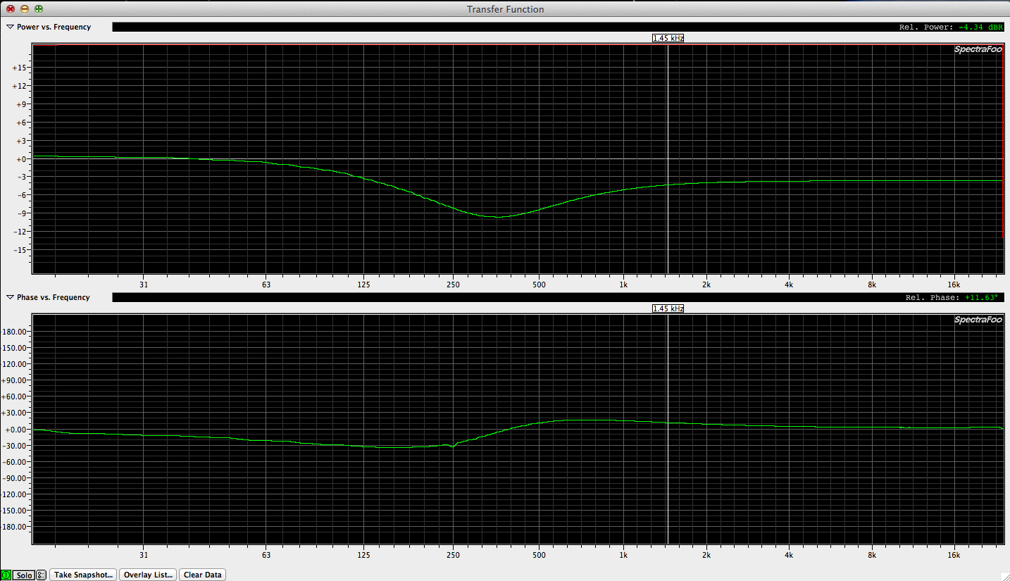
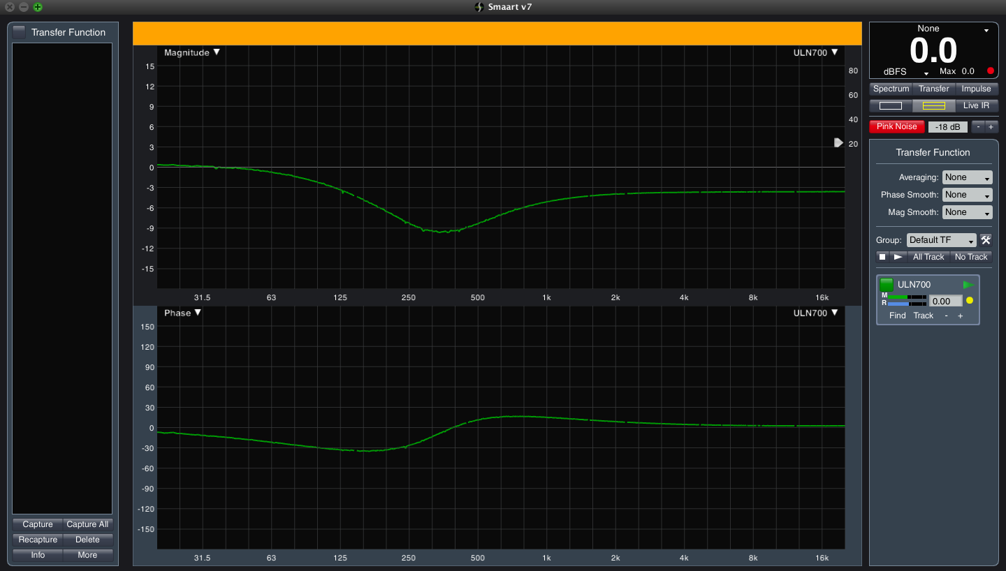
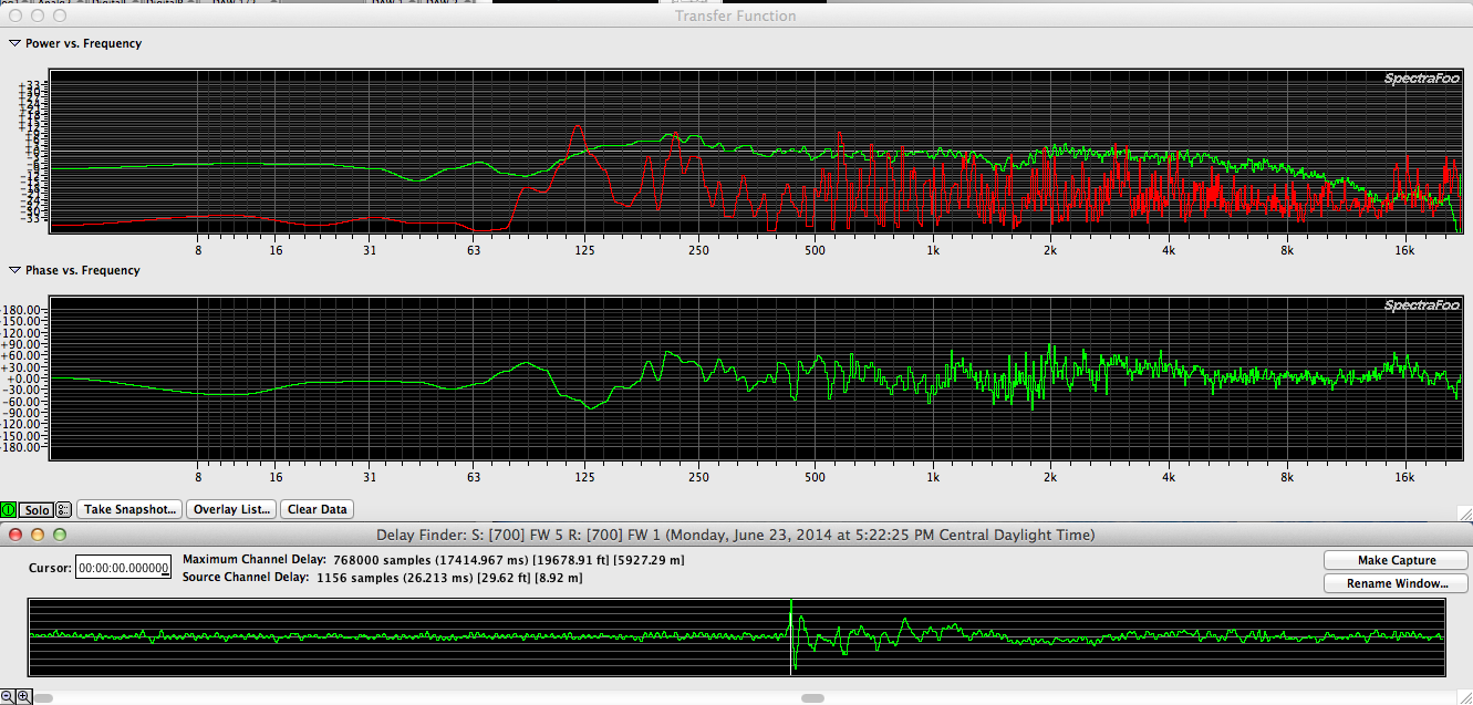
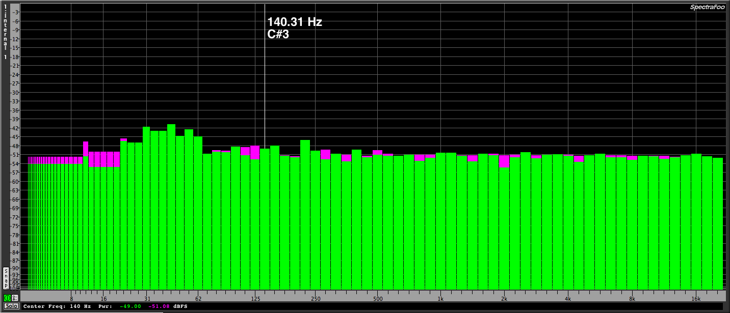
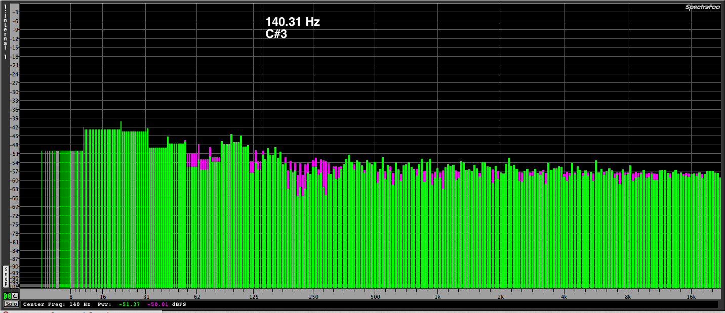
This evening I setup my measurement rig & patched one channel as a loop out / in with nothing more than a cable. The other channel had the KP1 Kickpad adapter inserted in the middle of two cables. Since I’m demoing Rational Acoustics Smaart 7 at the moment, I made measurements with both Spectra Foo & Smaart 7 to compare the two apps side by side. In case it’s not obvious, the upper trace of both measurements indicate the frequency response. The lower traces indicate the phase response.
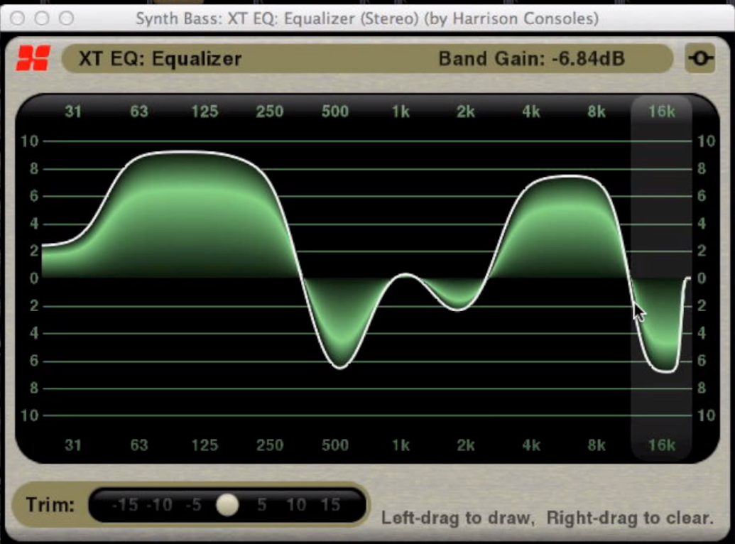
Interestingly this frequency adjustment would be hard if not impossible to accomplish with a console’s channels trip EQ. Even 4 band parametric EQ wouldn’t achieve the same curve because flat filters aren’t typically available on audio consoles. I can think of only (2) flat filter options I’ve seen in the audio DSP world. All based on modern DSP (digital signal processing).
1. Harrison’s EQ plugins for Mixbus is unique in that instead of being able to adjust level, frequency & Q parameters, your interface is the equivalent of a pen:
Harrison Mixbus EQ plugin
Harrison Mixbus EQ – Youtube video
Harrison Mixbus Mastering EQ plugin
Harrison Mixbus Mastering EQ – Youtube video
2.Lake’s MESA Processing:
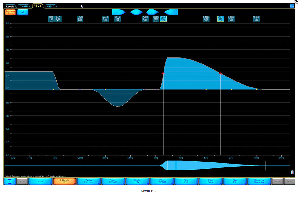
Sadly neither of these options are available to the general public in a form that can be added to a kickdrum channel on a live console so for those who want a simple passive EQ / PAD device designed specifically for use with a kick drum mic, VIVA LA KICKPAD!
Spectra Foo Complete / Smaart 7 comparison
The screenshot below shows a measurement made with both Spectra Foo Complete and Smaart 7 at the same time.
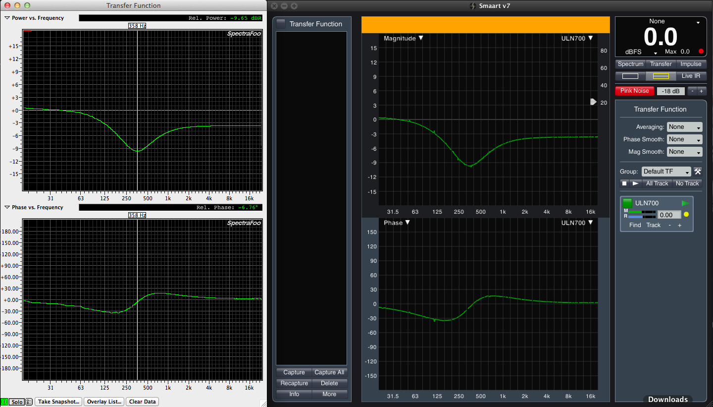
In order to get things to look comparable I had to adjust some of the default settings in Spectra Foo to match the default settings in Smaart 7. I’ve included a screen short of those settings below.
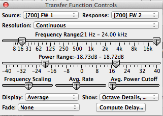
SIZE
Smaart 7 has a default minimum size which is rather large on a MacBook Pro 15″ Screen. Spectra Foo is infinitely size adjustable. I looked for a way to kill some of the side bars in Smaart but didn’t find any.
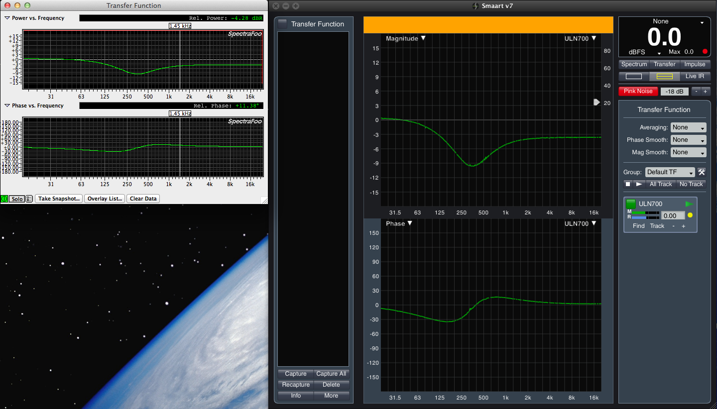
Here is a comparison of the two apps maximized for my MacBook Pro 15″ screen.
Some of the exciting features of Smaart 7 which are likely important enough to purchase it are as follows:
Live IR – The impulse response updates as the mic is moved
Delay Tracking – The delay time updates constantly
For live audio measurement purposes, this is pretty spectacular.
Some exciting features of Spectra Foo include the “studiocentric” tools. Keep in mind that Spectra Foo was born as a Pro Tools measurement plugin & became a stand alone app.
I see good reasons to have both apps & with (2) you can verify one against the other to make sure your rig is working properly.
A win/win situation.
Metric Halo – ULN2 self measurements
In order to measure the latency & A/D DA conversion quality of an interface, you can loop out of the interface & return the signal to an input.
The following are latency measurements at the (4) different sample rates:
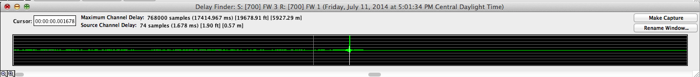 44.1k – 1.678 ms
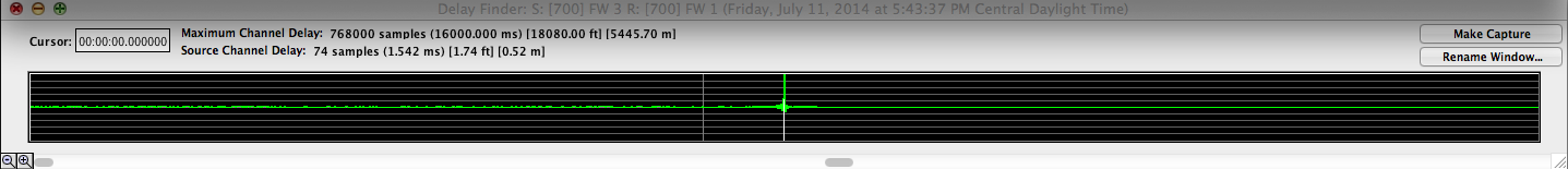 48k – 1.542 ms
 88k – .839 ms
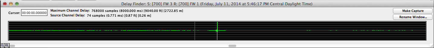 96k – .771 ms
Obviously if you want the lowest latency possible, you should run at a sample rate of 96k.
Next let’s look at the frequency & phase response at each sample rate.
Metric Halo related
These videos are fascinating. An interview between Metric Halo’s BJ Butler & Stephan
Tech Talk #1: The digits in digital audio
Tech Talk #2: Fixed and floating point audio
Tech Talk #4: Are all digital EQs the same? Part 1
Tech Talk #4: Are all digital EQs the same? Part 2
Open back guitar cabinet
I’ve never much liked an open back guitar cabinet for my own rig but there are many classic designs that are open back designs.
Open back means that the speaker is acting like a dipole.
Digital Latency
I would guess that the debate over which sounds better, digital or analog, will never be truly settled but one thing is clear.
Analog = instantaneous
Digital = delayed (latency)
You can route an analog signal thru a rack full of analog gear & the signal will still arrive at the final destination in (0) time. The electrons are traveling at almost the speed of light.
Due to the nature of digital conversion. Analog to Digital / Digital to Analog, a digitized signal cannot arrive in (0) time. There is inherent latency. The best we can hope for is to minimize the latency & use it when possible to our advantage.
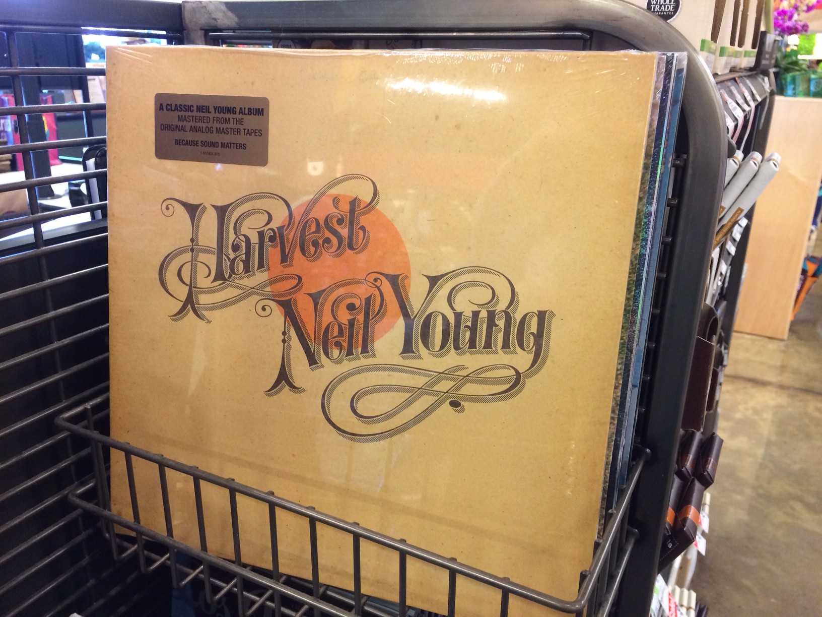
One thing is for sure. Digital audio is here to stay & analog audio is a dying breed although there is hope when I see this in a grocery store check out line in 2014.
Some good news. The CD standard of 16 bit / 44.1k sample rate is fading. It can be argued that the 16/44.1 CD standard was never acceptable. A decision based on A/D D/A conversion technology at the time & cost savings.
I recently watched a video by Metric Halo’s own BJ Butler who stated that 24bit / 96k audio is as good as we need for capturing audio correctly. If you don’t want to watcht the whole thing, FF to around 17 minutes.
Metric Halo’s BJ Butler discusses sample & bit rates
@ a sample rate of 96k, latency drops by 1/2 compared to an audio device that is running at 48k. Even less latency @ 96k than at 44.1k. And the latency at 96k is small enough to be acceptable. 96k also sounds good so as long as the industry continues to move toward 96k sample rates as a standard, I think we will live through the growing pains of abandoning our analog roots & becoming digital sprouts:)
How much less latency are we talking about?
How do we measure the latency in and out of our gear?
How much latency is acceptable before it begins to cause issues?
For studio purposes where musician’s are monitoring themselves as they perform, the lower the latency amount the better. Some humans are bothered by even small amounts of latency when monitoring themselves (singers especially) where as some humans don’t seem to mind. What we do know is that when you’re trying to play or sing in time, the accuracy to which time is presented is important so I think we should be doing everything possible to avoid any unnecessary latency for monitoring purposes.
Delay PA to backline
The precedent effect states a few things that are important to us in the audio reinforcement realm.
http://en.wikipedia.org/wiki/Precedence_effect
“The precedence effect or law of the first wavefront is a binaural psychoacoustic effect. When a sound is followed by another sound separated by a sufficiently short time delay (below the listener’s echo threshold), listeners perceive a single fused auditory image; its perceived spatial location is dominated by the location of the first-arriving sound (the first wave front). The lagging sound also affects the perceived location. However, its effect is suppressed by the first-arriving sound.”
In a nutshell, when two signals arrive together they act like a single signal. When one arrives first it’s perceived as the origin of the signal even if the secondary signal is louder.
This has many important implications for live sound.
IF the PA is in front of the band & IF the PA signal arrives before the direct signal coming from the stage (guitar amps, drums, bass amp, etc…) the origin of the total sound will appear to come from the PA.
IF we delay the PA (using DSP) back to the physical backline or further, the sound origin appears to come from the stage instruments.
I have seen suggestions that we should delay the PA to the drum kit, guitar amps, etc…
Since a drum kit is a 3 dimensional instrument (has height, width & depth) * a guitar amp will typically have a single dimension, I would be inclined to delay to the middle of the drum kit.
How?
The best way is to place a speaker at the center of the stage on the line at which you want to delay too. Use that as your (0ms) measurement & then delay the PA until it matches. It’s amazing what a difference doing this simple delay procedure makes in focusing the audiences attention to the band & not the PA.
Here is the basic procedure:
Place reference speaker at center stage
Measure pink noise through reference speaker with mic placed out in the house & note delay time
mute reference speaker
Send pink noise thru PA & measure (same mic position) and note delay time
Compare reference speaker delay time with main PA delay time
Delay main PA until it matches delay time of reference speaker
If you can’t measure, don’t have a reference speaker or simply don’t have time, you can guess how far back the reference line is and delay accordingly. If when you look up & listen to the band @ sound check, you feel the main PA is either too late or still too early, adjust & listen again.
Keep in mind that in this day and age of digital consoles & digital signal processing, there is an inherent amount of latency by default. Typically your reference speaker wouldn’t be fed a signal from the main PA DSP so there is latency involved with the main PA that might not be involved with the reference speaker signal. For example, if you fed the reference speaker off an aux or matrix that bypasses the main PA DSP device. In that case, one system has more inherent delay than the other. Something to keep in mind.
Due to digital signal latency, you may find that the main PA is already arriving late enough that there is no need to add further delay to the signal to align it with the reference target point. If so, fine.
If a signal passes through enough digital processors in route to the speakers, you could easily find that your PA is significantly behind the band’s backline gear already. If so, there isn’t much you can do but physically move the band or the PA.
DI Boxes
DI (direct input / direct injection) boxes are not created equal. Most cheap DI boxes are passive (no electronics) and use relatively poor quality transformers.
In some cases using a cheap passive DI may be fine but in some cases you will need something better.
Let’s split DI boxes up into a few categories.
Inexpensive passive
Expensive passive
Inexpensive active
Expensive active
Inexpensive tube based
Expensive tube based
Let’s draw the line between expensive & inexpensive at $100. That should separate the mice from the men.
Ignoring tube based DI units,
Here are my favorite DI options for live work.
Radial Engineering -JDI
http://www.radialeng.com/jdi.php
Radial Engineering – J48
http://www.radialeng.com/j48.php
Radial Engineering –
Guitar amp comparison
If you want to get one guitar amp to sound like another, one of the measurements you can make is to send pink noise to each amp & measure the speaker output via your measurement mic.
The procedure would be as follows:
Play your guitar through amp A & adjust until you like the sound
Send pink noise to the input of amp A & capture the frequency & phase response
Send pink noise to the input of amp B & capture the frequency & phase response
Now adjust the EQ & gain settings until the measurement matches that of amp A.
It’s possible that the EQ adjustment of amp B won’t allow for a complete match.
It’s possible that the two amps will be different enough in tonal flexibility that they won’t match.
It’s possible that the two amps will have different distortion characteristics in which case they won’t match.
Regardless you should be able to get as close as possible by measuring the two amps.
While you’re setup to measure, it would be wise to take measurements with all the EQ parameters at their minimum & maximum settings & make captures of each one by itself. Then take the same measurements & make the same captures using different minimum & maximum settings between EQ bands. This way you will know exactly what knob is adjusting what range of frequencies & how they react to each other.
Studio Monitors
Engineers rely on studio monitors for accurately representing their mixes for the general public.
Things to consider when placing studio monitors?
1. secondary reflections off the walls, ceiling & floor.
2. secondary reflections caused by your furniture (console / desk / etc…)
3. locating monitors up against a wall or in a corner will add low end
4. locating monitors in non symmetrical locations (one in a corner / one along a wall) will create anamolies in the stereo image.
When it comes to accurate reproduction of an audio signal thru the air, reflections are bad. When it comes to making mixing decisions, the better the phase & frequency response of the monitoring system, the better one knows they can trust their mixing decisions will translate universally to the average playback system (car stereo, home stereo, Ipod, Iphone, etc…)
One thing is assured. Any speaker placed in a acoustic space will interact with the space. At worst, this interaction will cause frequency imbalances & reflections that smear the time domain information. At best, the engineer will still have to pay close attention to placement, height & reflections. In live audio it is now common practice to have a multichannel DSP for system processing & frequency response correction. It only seems logical that the same should be true for studio reference monitors but I am unaware of this as a generally accepted practice. Regardless, I would suggest that studio reference monitors should be corrected with DSP since the laws of physics don’t change just because your purpose is different. Maybe some day a DAW (digital audio workstation) will include master buss processing to correct reference monitors for frequency response. Better to correct the speakers once & maintain that correction than to try to fix the frequency imbalance per channel.
Likely the most popular studio reference monitor of all time was the Yamaha NS-10.
A case for passive stage monitors
I’m not sure I’ve ever seen a band rider that doesn’t state, “NO PASSIVE WEDGES”. Option B? “BIAMPED WEDGES”.
A passive speaker is one that has an internal crossover. With a biamped speaker you perform the crossover filtering before the amp channels.
In theory, a biamped speaker can provide superior sound. With a passive crossover, you’re losing power passing through the passive crossover network. With a biamped speaker, each transducer can be fed straight from the amp.
So biamped is more efficient as a concept but in this day and age of cheap & high quality power amps, I’m not sure efficiency is a concern.
I would guess that a biamped speaker can probably get louder than it’s passive counterpart but not sure that is actually the case.
Passive or Biamped?
Based on my experiences with biamped stage monitors, I would have to assume that very few sound companies know how to biamp a stage monitor correctly. If I had a dollar for every time a set of biamped speakers sounded completely different, I’d be retired by now.
The principles behind building a passive crossover network are well known & any decent speaker designer can do it.
This means that while a speaker with a passive crossover network might be limited in some ways, a batch of fully functional passive stage monitors should all sound the same. If the speakers haven’t been serviced incorrectly, the phase of all the transducers should be correct.
With biamped wedges there are many points along the signal path for things to go wrong. There are (4) conductors between the amps and the speaker. The active crossover points themselves can be wrong. The levels between the amp channels can be wrong which changes the crossover point & the sound of the stage monitor.
When I see a local monitor engineer adjusting the balance between the woofer & the tweeter at the amp, I know something is wrong.
For a stage monitor sitting on the floor, there should be no guess work involved with crossover points & transducer levels & they should all be the same. Any discrepancy should be adjusted somewhere upstream of the crossover & amp.
The perfect speaker
Prior to beginning to understand how speakers interact with each other & with the acoustic environment around them I thought that in a perfect situation, the perfect speaker would require no EQ.
Knowing that there is no perfect speaker or perfect speaker combination or perfect acoustic situation is vital to being able to accomplish a “best care scenario”.
For the sake of experiment, lets say we own a perfect speaker. A single transducer that can produce 20hz to 20k.
Perfect frequency response.
Perfect impulse response.
Perfect phase across the entire audible range.
Question:
Where?
If you design a speaker to be on the floor, raising it on a speaker stand means that it’s now low end deficient because it was relying on the coupling with the floor. If you design a speaker to be used on a speaker stand, putting it on the floor means it now has excessive low end. If you design a speaker to be listened to in free space, putting it up against a wall will mean that it’s low end changes. A corner? Even more low end. On the floor in a corner? Even more low end.
The solution that comes the furthest so far is a self powered speaker that has presets to compensate for acoustic loading.
Twist & Shout – monitor mixes
I made a quantum step forward in my measurement pursuit today. I have been planning on measuring all monitor mixes before the band arrives for a long time but never made it before I ran out of time before.
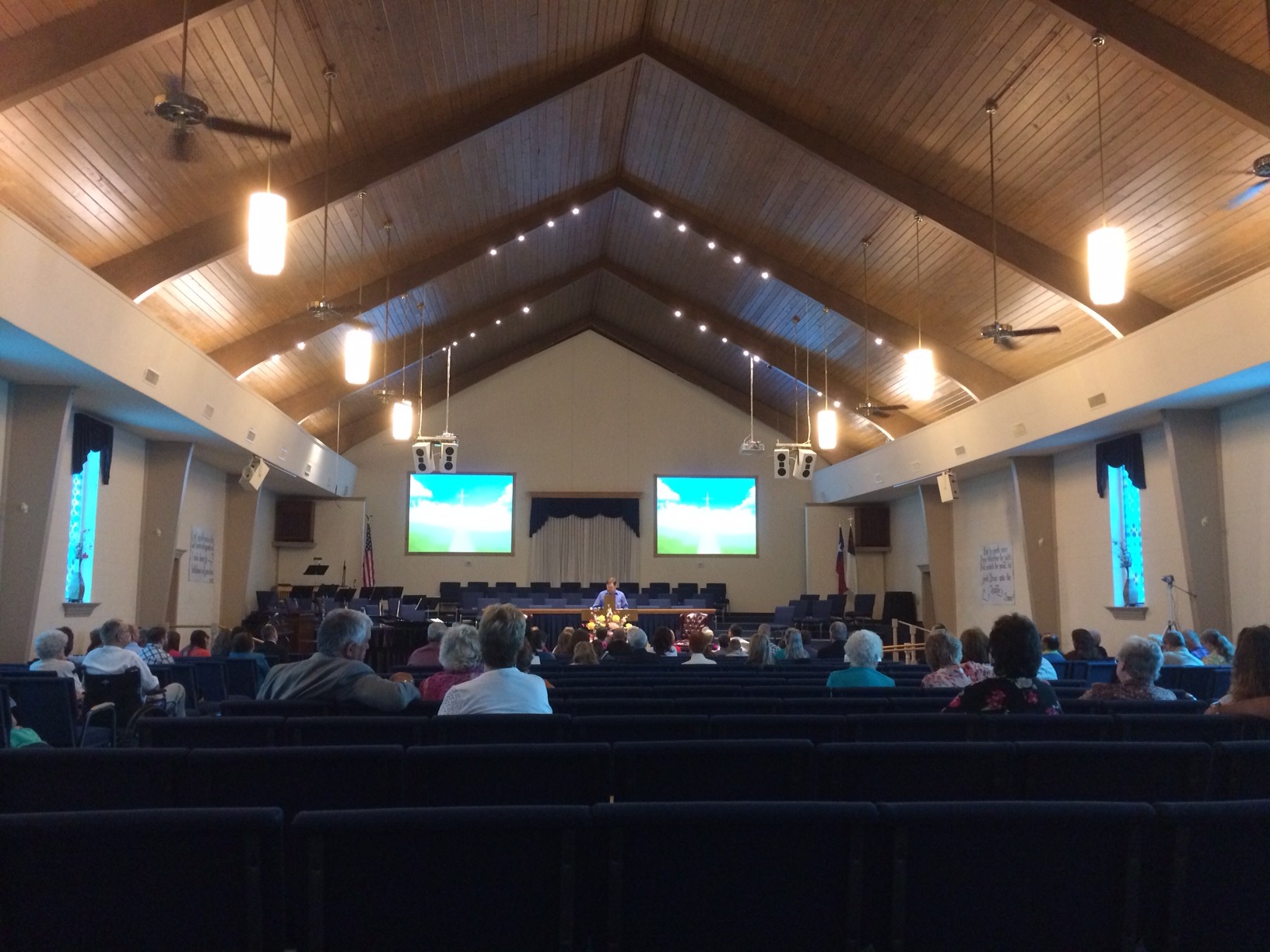
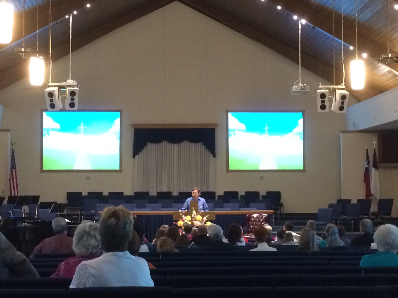
For this gig, I use my Mac laptop for Qlab video & audio playback in addition to Spectra Foo Complete. We typically have either (1) center video screen / projector or (2) side video screens / projectors. I don’t know why I haven’t thought of this before but I realized that I could drag FOO onto the secondary video window & see it from the stage.
My original intent today was to roll my rig to the stage on a road box after I tuned the FOH rig. This way I would be able to see my screen as I worked on the band’s monitor mixes.
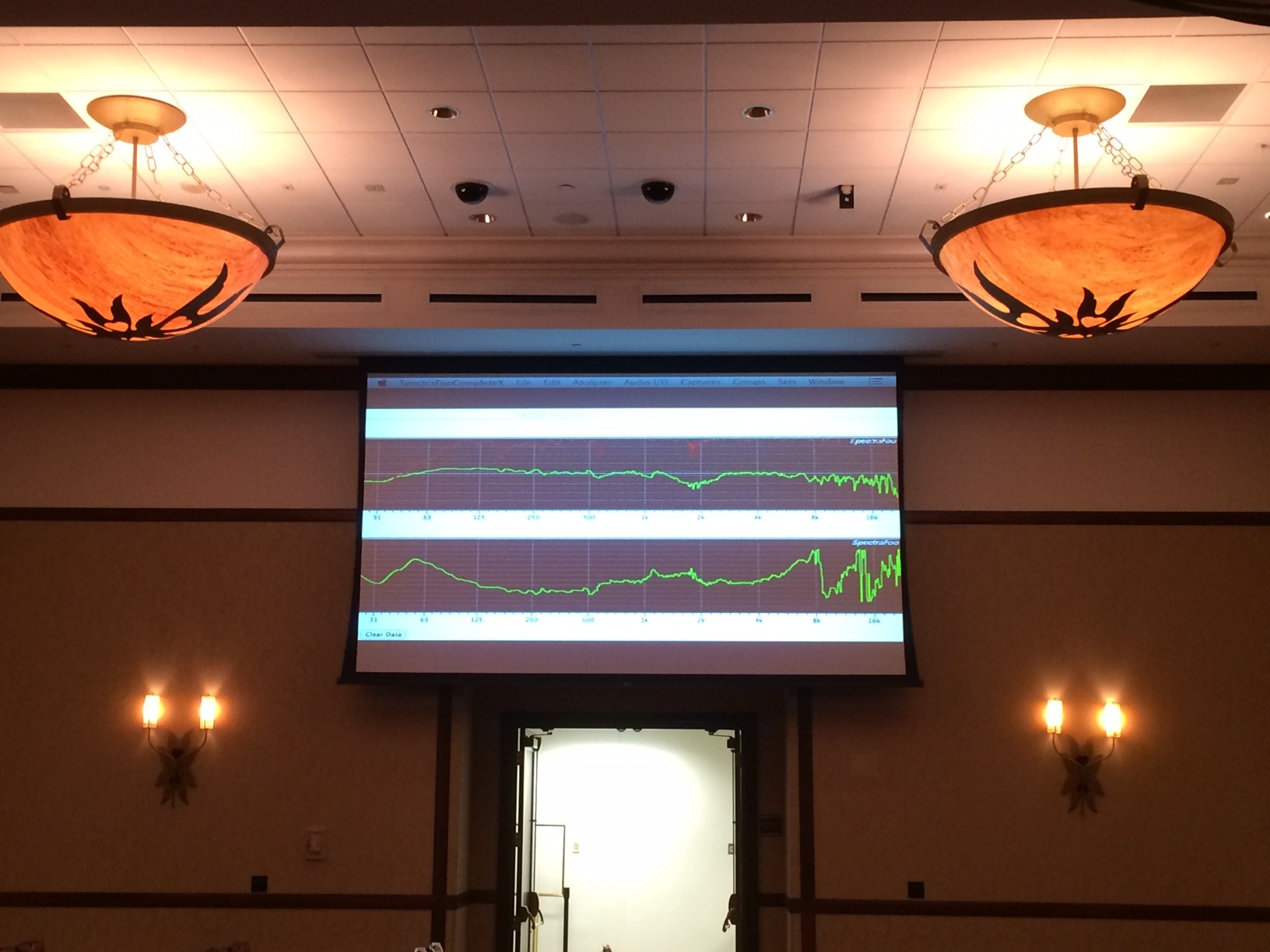
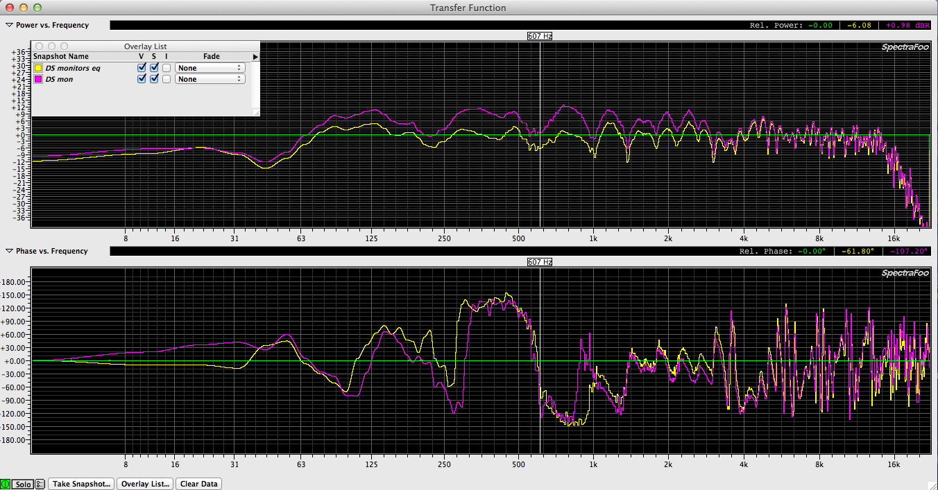
Being able to see a huge screen on the side wall was incredibly helpful as we could see the frequency response trace as we adjusted the crossover levels between lows & highs. I will need to figure out how to do recalibrate my delay offset remotely with my Iphone since moving the mic without doing so ruins the phase response trace.
Using an Aux on the FOH console, I sent pink noise generated in FOO down the talkback line to the monitor system. I had already extended my measurement mic cable to reach the stage plus some extra slack.
The stage monitors were a custom built 2 way design. 15″ / horn biamped wedges. Note to self. Don’t remove the X from a speaker without verifying it’s fully functional again. Even though I was told I could because it was fixed, I didn’t & it wasn’t…
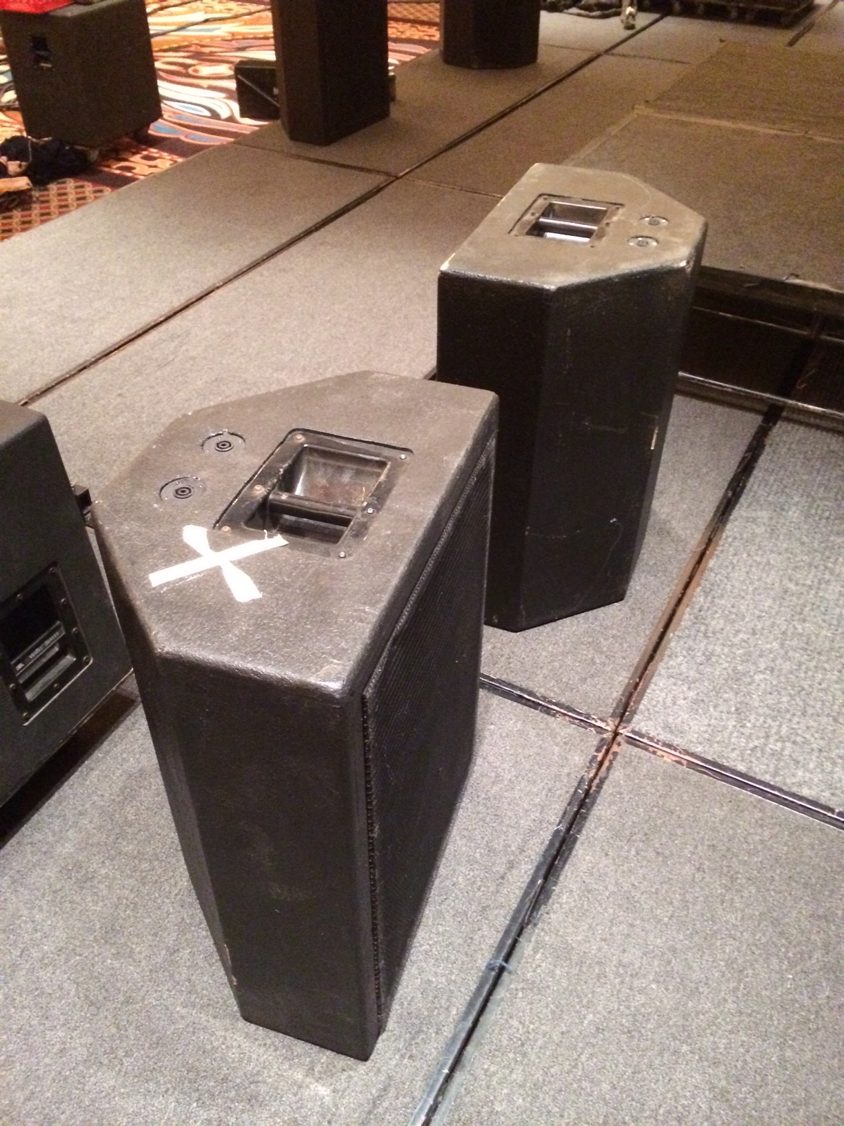
Here is a photo of the setup for measuring Mix 1.
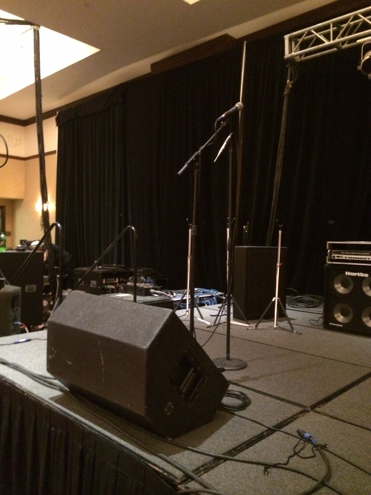
By measuring each monitor mix prior to the band’s arrival. I was able to learn a lot about how little I know about recognizing crossover points, phase, etc… I was also reminded of how absurd it is to use 31 band graphic eqs to process monitor mixes. Maybe some day that concept will be replaced with modern knowledge. For this gig, I didn’t have a lot of time to spend tuning the monitor mixes so I used the graphic eqs to flatten the peaks as much as possible.
Frequency Response / Phase Response / Impulse Response
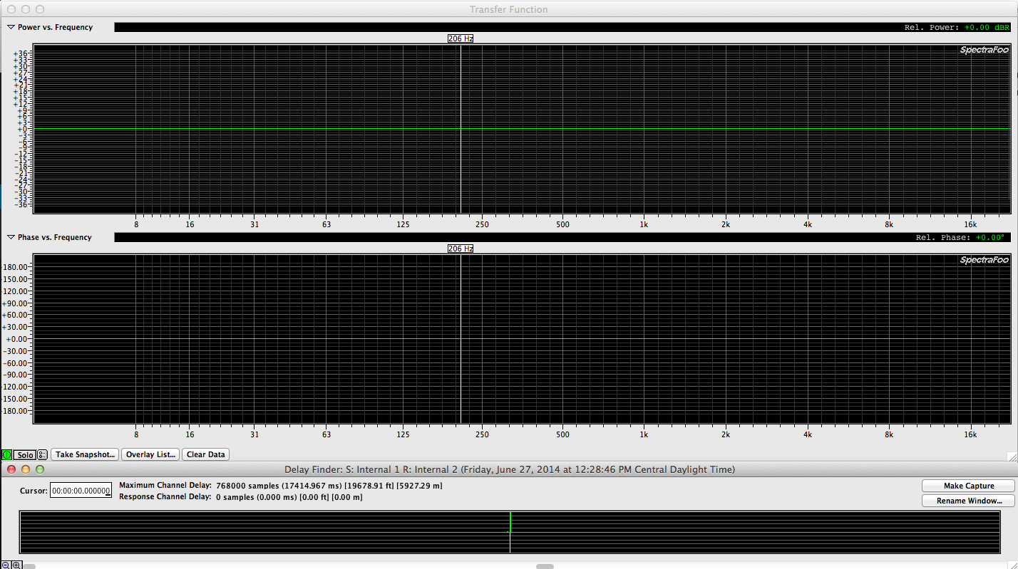
Below are some Spectra Foo Complete transfer function screen captures to illustrate how the (3) different windows available within a transfer function relate to each other.
The top window shows frequency response (green) & coherence (red).
The middle window shows the phase response (green).
The bottom window shows the implied impulse response (green).
Here is an example of a perfect set of captures. This was made by measuring the internal pink noise generator inside the program against itself.
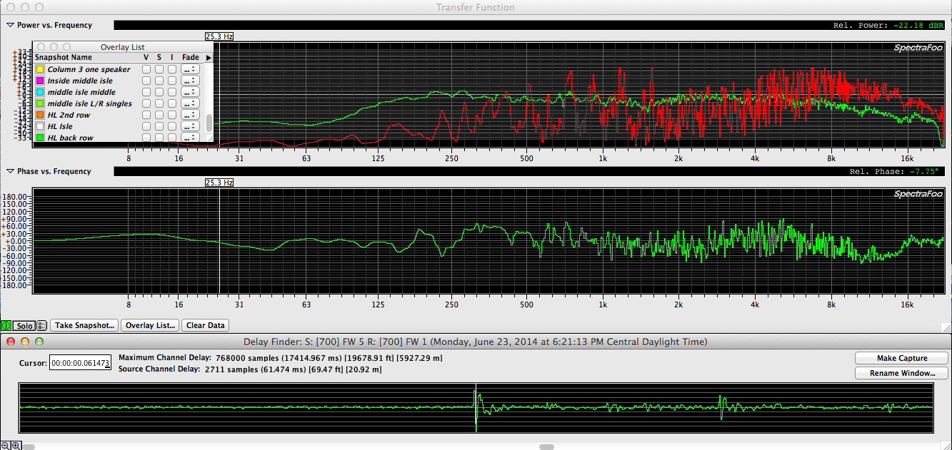
You’ll never see anything like the above screen capture in real life conditions. Instead you will see things like what is shown below.


RTA – Real Time Analyser
An RTA shows the frequency response of an electronic or acoustic system in real time. The following screen captures are the various scaling options for Spectra Foo Complete’s “Spectra Graph”, their take on an RTA. As you split up the scale, you get finer & finer resolution. 1/3 scale being the industry standard since it matches the industry standard 1/3 graphic EQ.
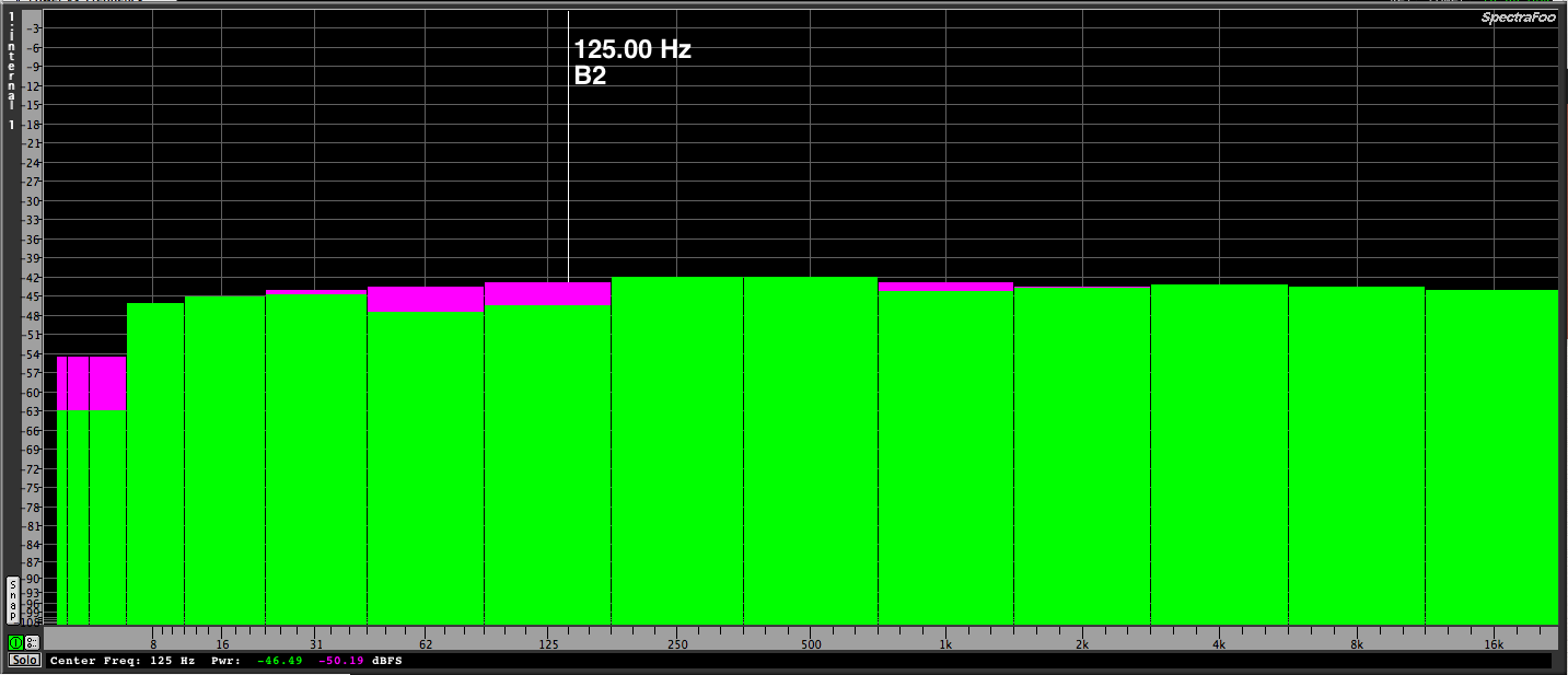 1 octave scale
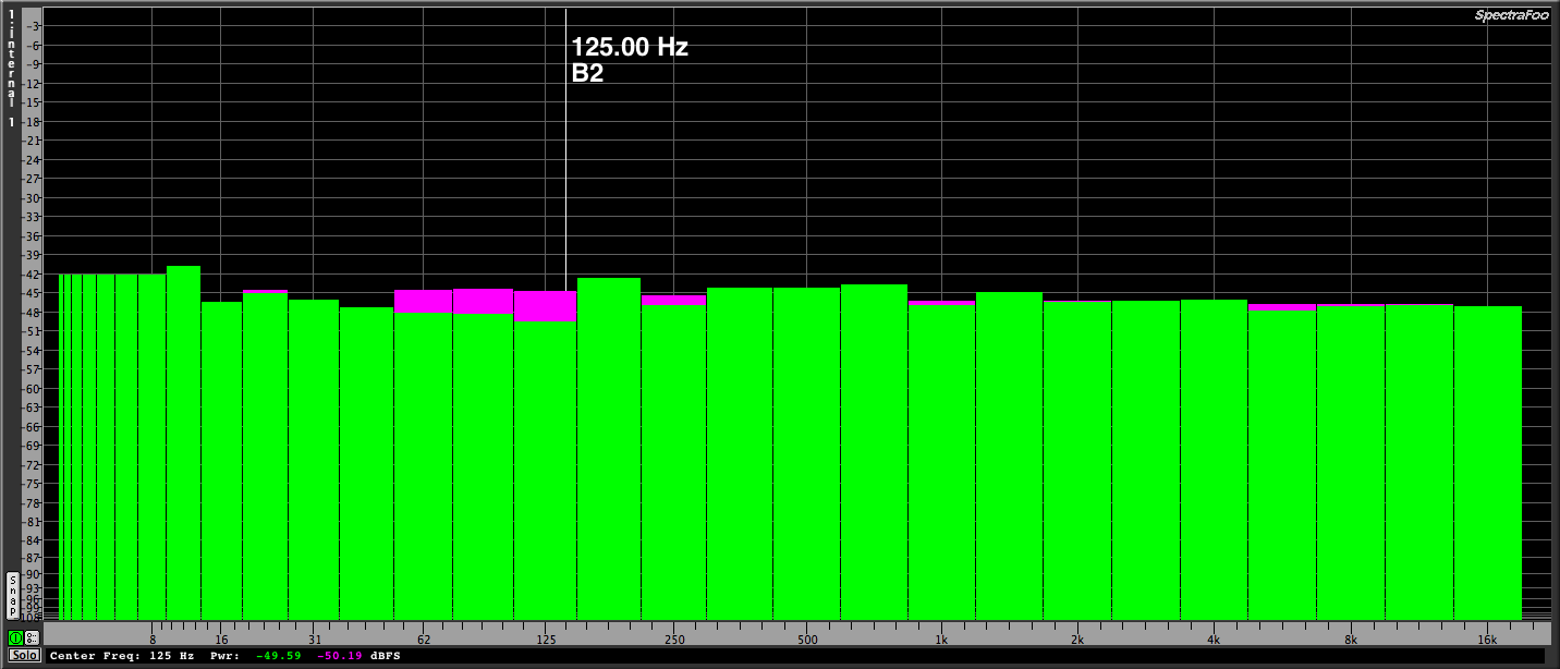 1/2 octave scale
 1/3 octave scale
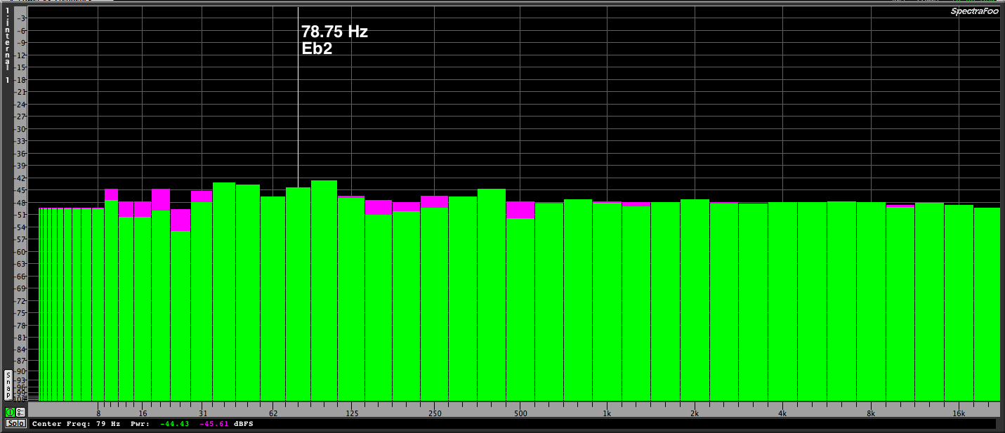
 1/6 octave scale
 1/12 octave scale
 1/24 octave scale
Initially RTA devices was a stand alone units but modern FFT measurement software packages include an RTA function so stand alone units are some what obsolete now. There are many RTA apps for Ios devices. An RTA is useful for recognizing feedback frequencies but is not the right tool for PA tuning. The right tool for tuning a PA is the Transfer Function because you can see impulse, phase & frequency response again a known value.
Friends don’t let friend’s tune PA’s with an RTA.
Less is more…
In 2007 I spec-ed and installed a PA system in a small local church during their renovation. The space is very live with the back & side walls being painted block. Wooden columns break up the walls & the wooden ceiling. The rest of the space is textured sheet rock. The only soft surface is the carpet on the floor. Since the side walls are parallel & the front & back walls are parallel, speakers need to be aimed at the ears of the congregation & no where else to avoid reflections & feedback.
The main PA design originally consisted of (2) custom speakers made by Toby Speaker Corp called “Blasters” and (2) Toby “Sheriff” subs (hidden inside the duct work race ways on the side walls). Due to my own ignorance on 2007, it was decided to add a second set of “Blasters” right next to the original pair & simply jump from one to another. The concept at the time was to cover the side seats closest to the stage with the second set of speakers but without an additional amp channel & additional DSP, that was a poor design choice. At the time of the install, I actually had a Smaart 4 license but I had no idea how to really use it. Instead I used the built in RTA functions of the dbx Driverack 260. Another poor choice. At least I didn’t let the “dbx EQ wizard” function do the system tuning.
After learning some critical concepts from working with system designers & also reading Bob McCarthy’s books, I was pretty sure that the best thing I could do for that system was to disable 1/2 the speakers & after a road trip was preparing to make the call. Instead, I got a call from the church requesting a site visit to address some wireless issues they were having. I headed straight over to catch their Sunday service. Sometimes the best time to do something is right now. I scheduled more time next day to measure & troubleshoot their wireless gear further. After careful listening I am certain the second pair of speakers don’t help anything & cause all sorts of other issues. The PA would have sounded much better if I had used (2) main speakers like originally planned for. Amazing what over complicating a system can do to ruin it’s response.
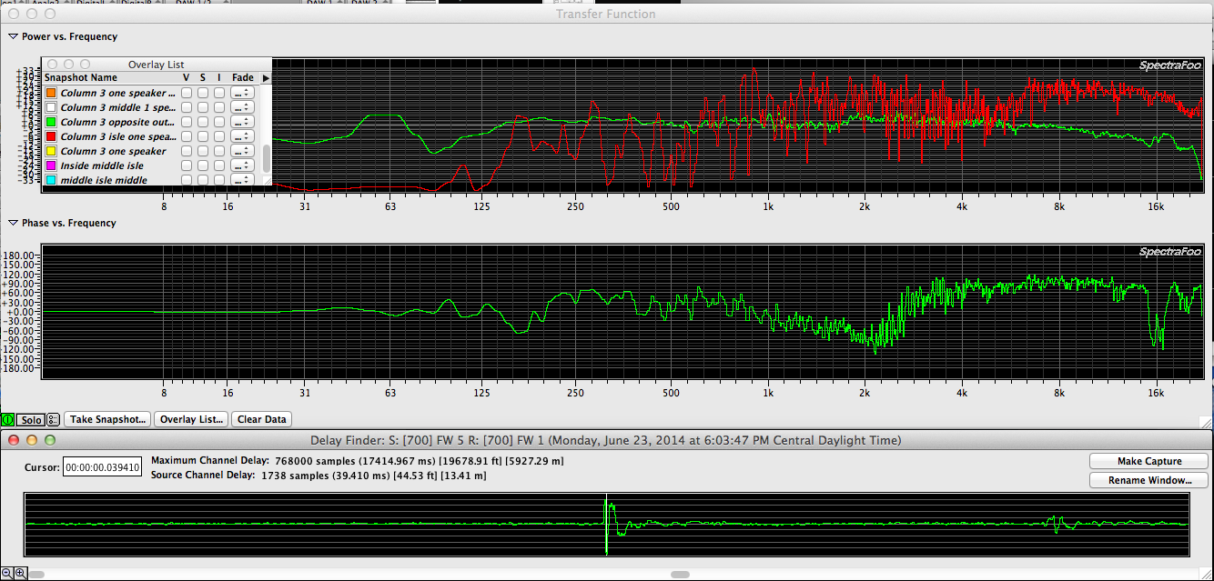
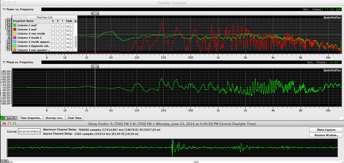
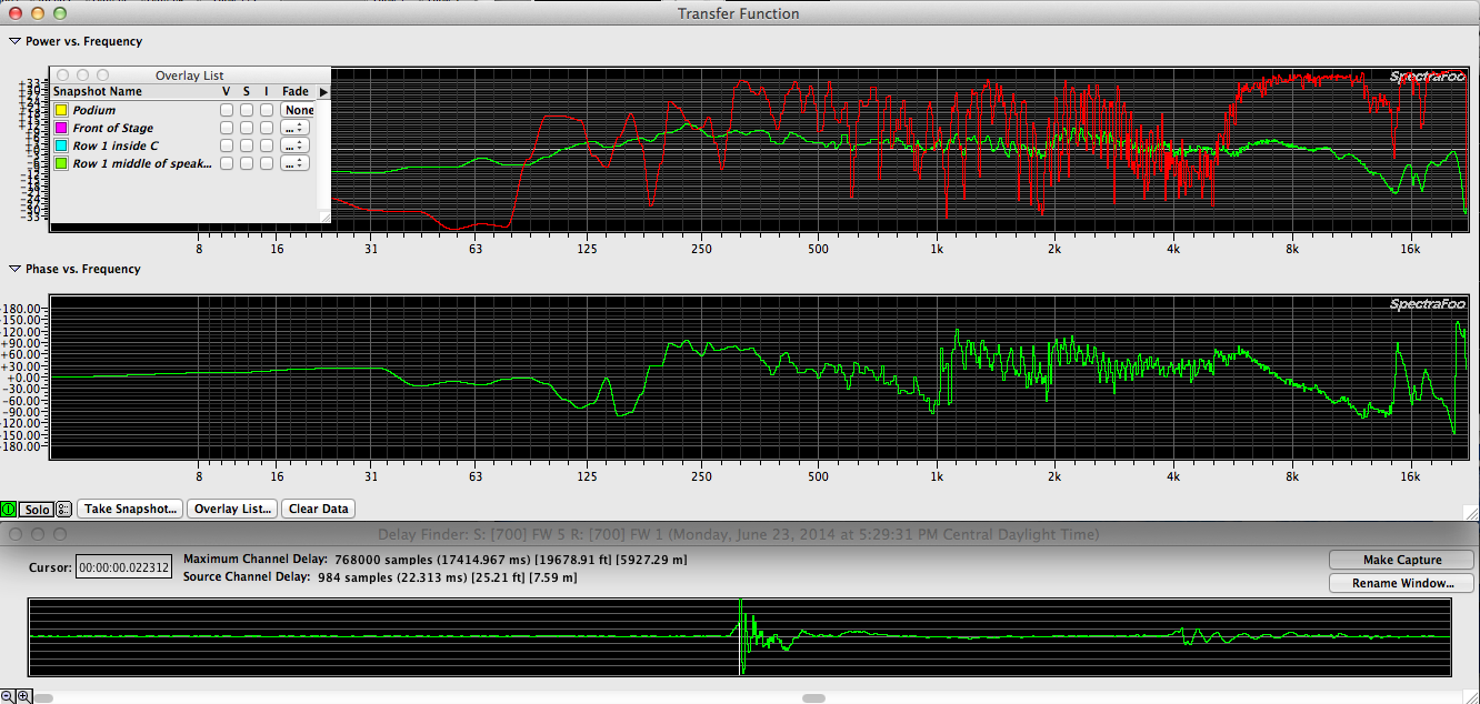
This following trace was taken on axis of the inside speaker with both of speakers plugged in. In this position the mic is still measuring both speakers but is somewhat off axis of the outside speaker.
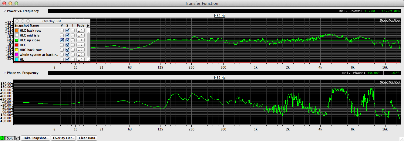
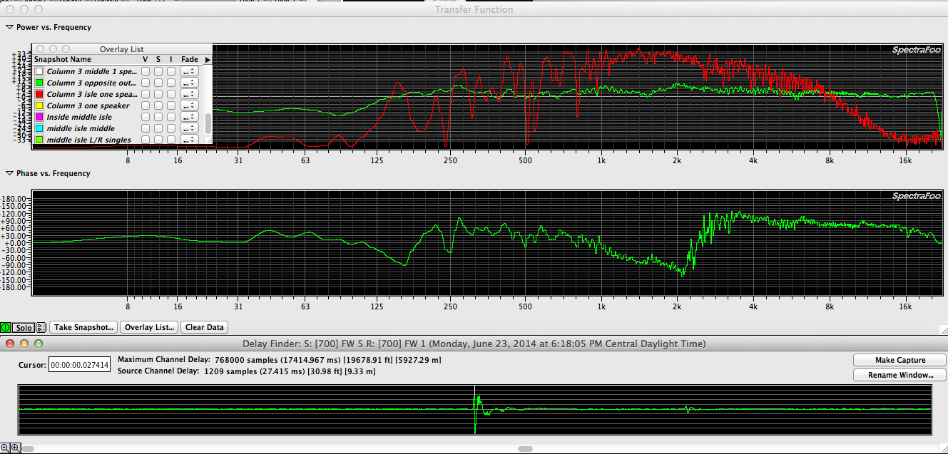
This trace was taken by moving the mic directly sideways to the side wall. Comb filtering?
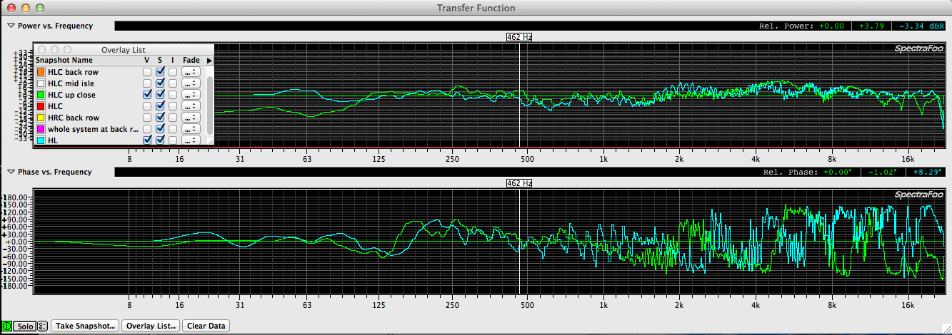
Here are the same traces overlapping. Notice that the high frequency response of the inside speaker is worse than the outside speaker measurement. This is surely due to phase cancellation & comb filtering.
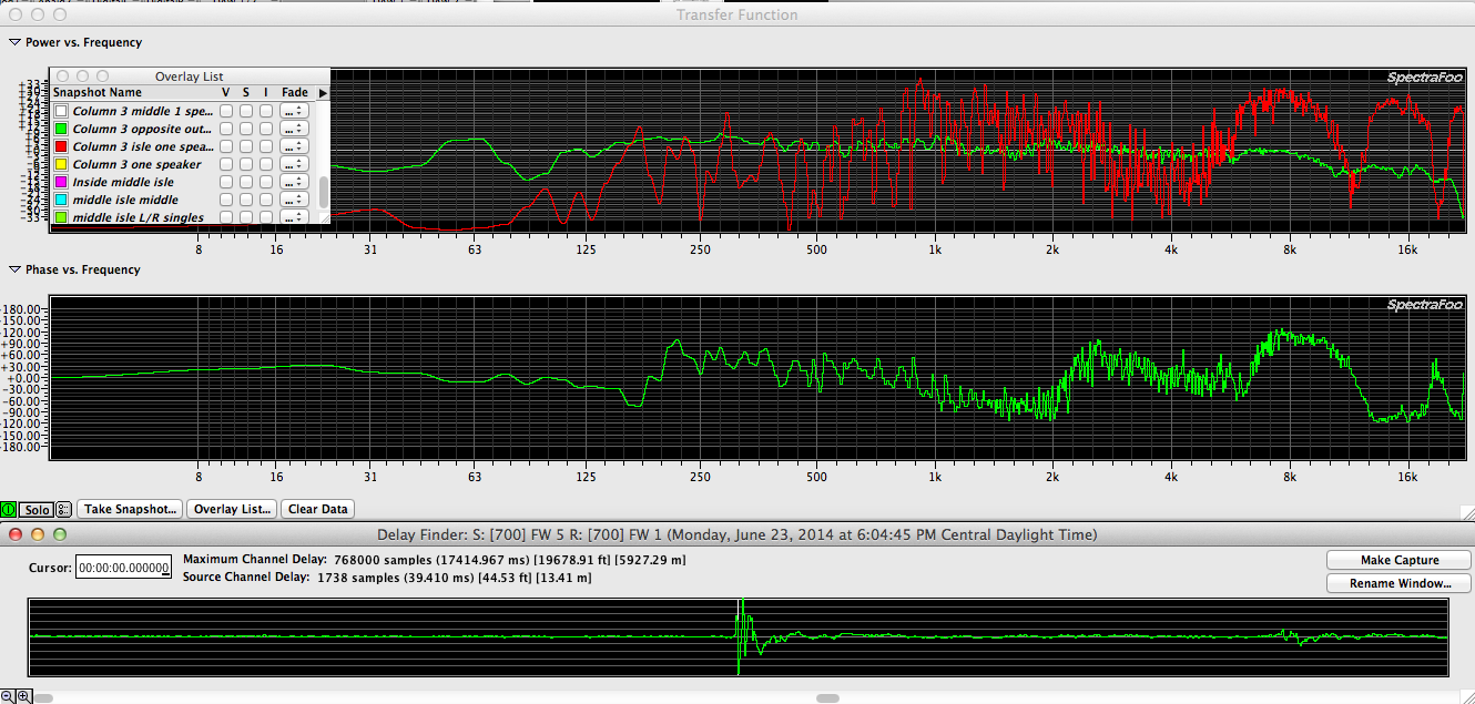
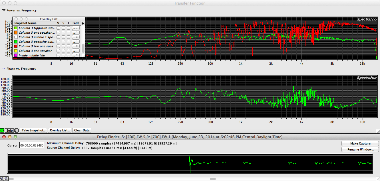
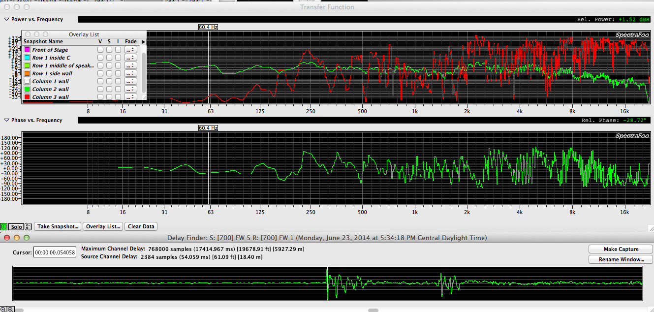
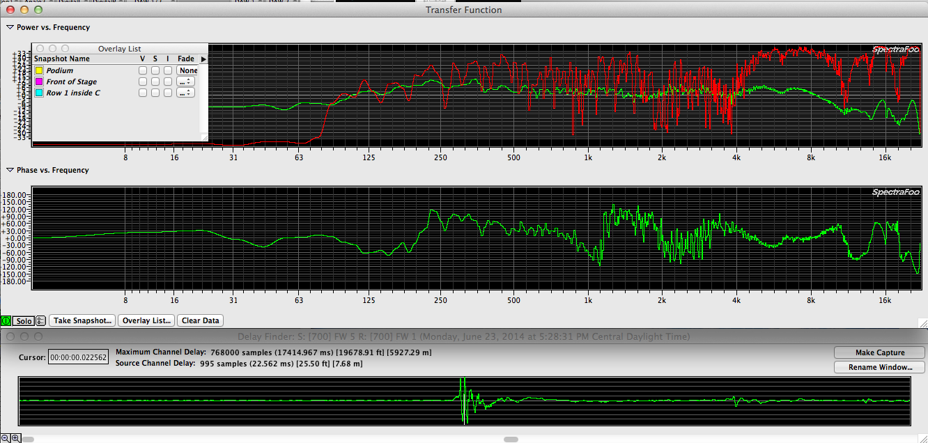
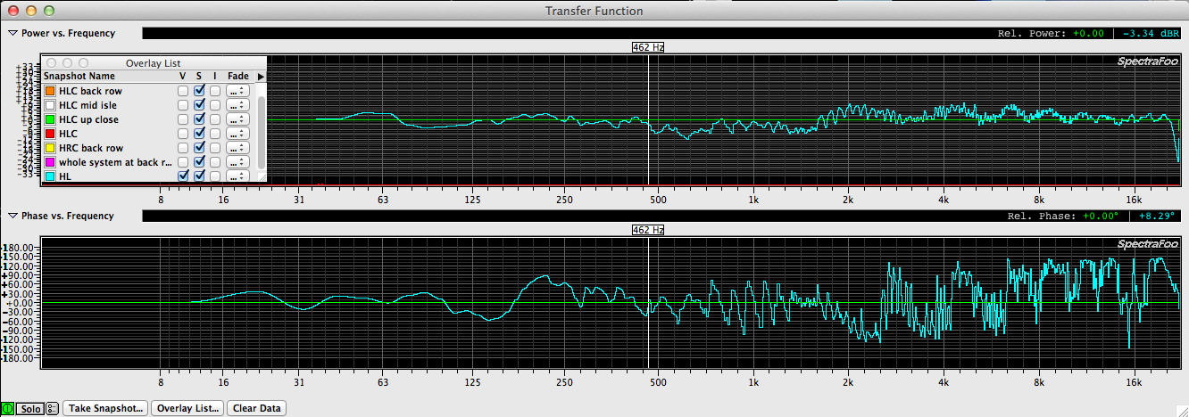
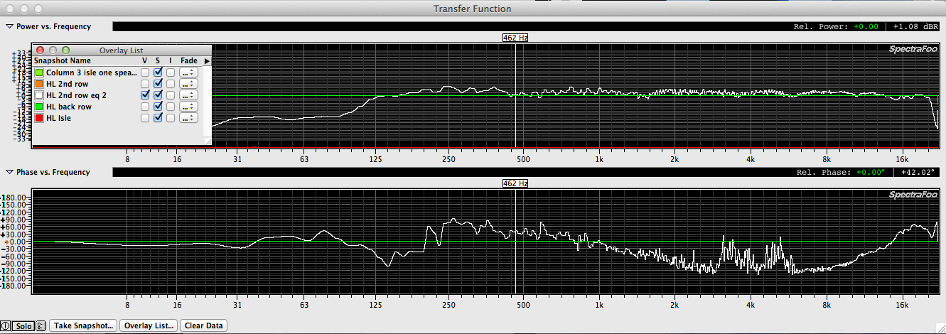
What happens if I unplugged the outside speaker leaving only (1) speaker on with the mic back at the on axis position of the inside speaker at the second row?
The result is kind of amazing actually. I wonder if that phase shift around 2k is due to the cross over?
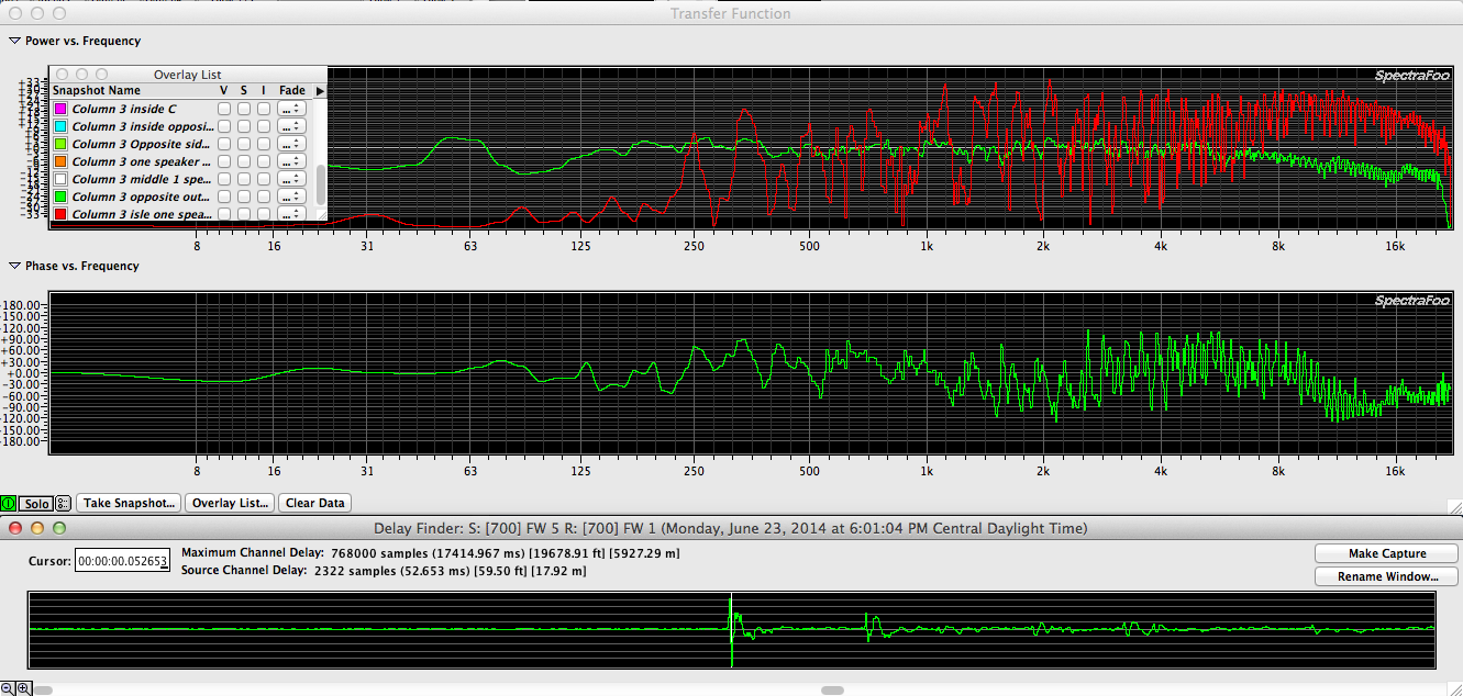
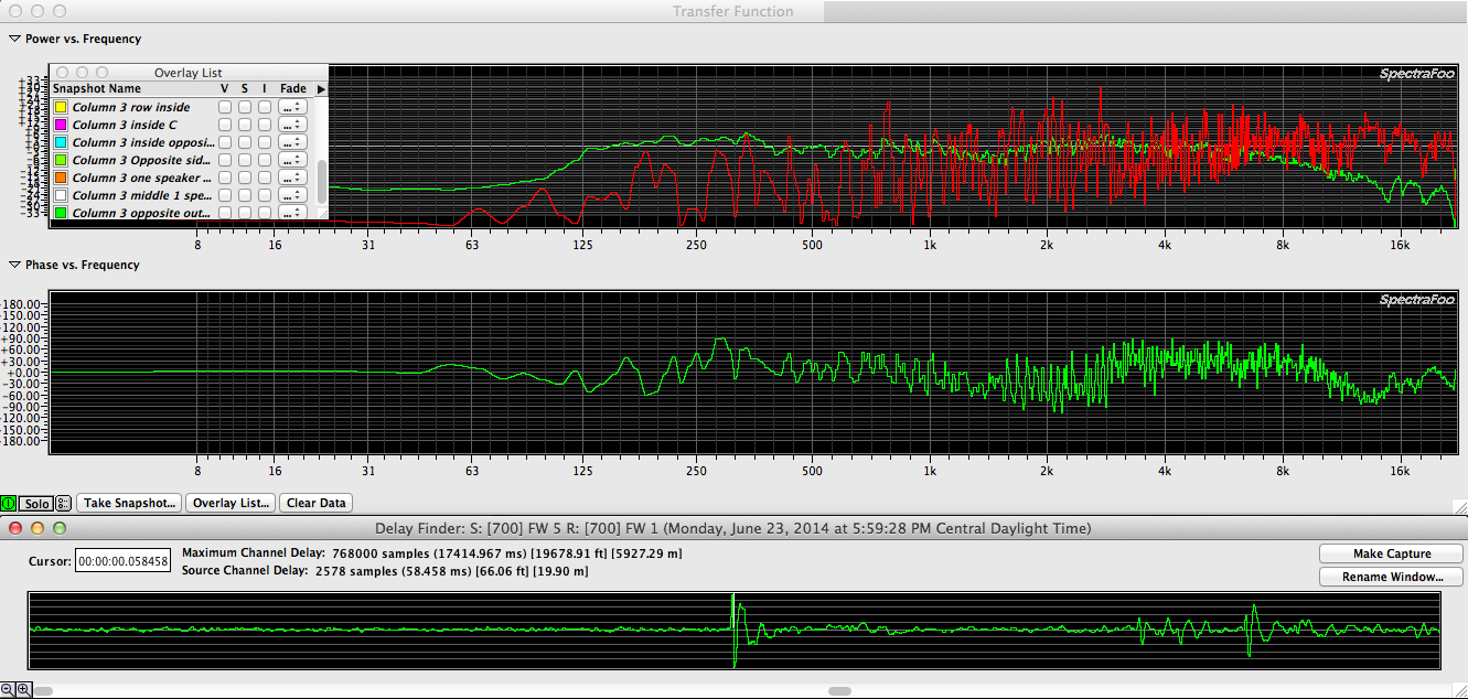
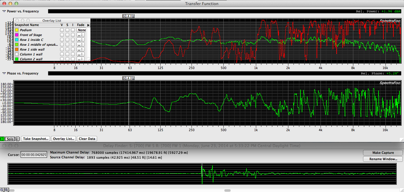
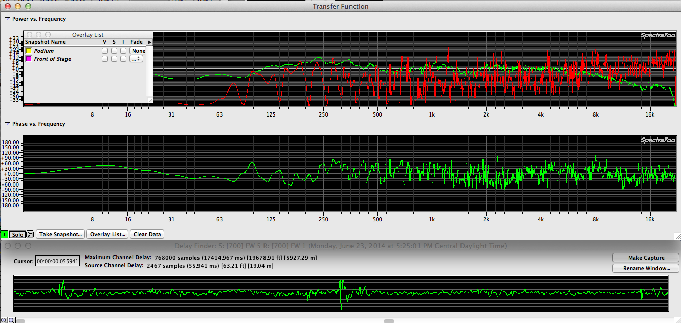
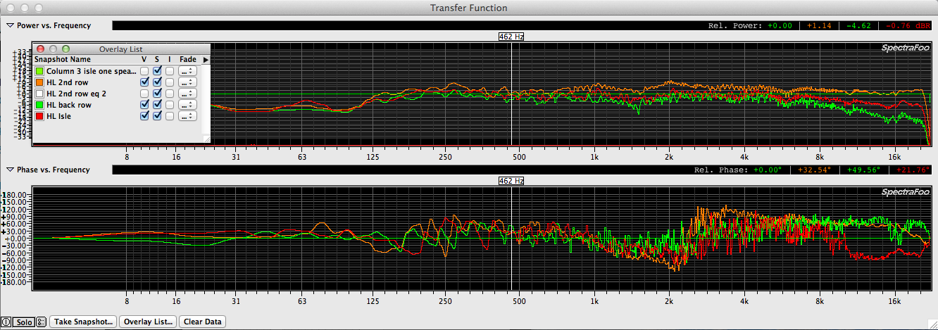
Moving the measurement mic directly away from the same speaker toward the back of the space, note that the high end starts to roll off due to distance (see red trace)…
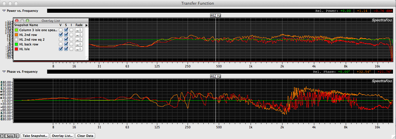
At the last row (see green trace), note that the high end has fallen off significantly. Roughly 75′ away from the main speaker pair. This space is a good candidate for a pair of delay speakers to add the missing high end back for the second half of the congregation. Especially considering that there is an isle right after the 7th row of seats. Literally splitting the seating area in 1/2 with about 6 feet of open area between them.
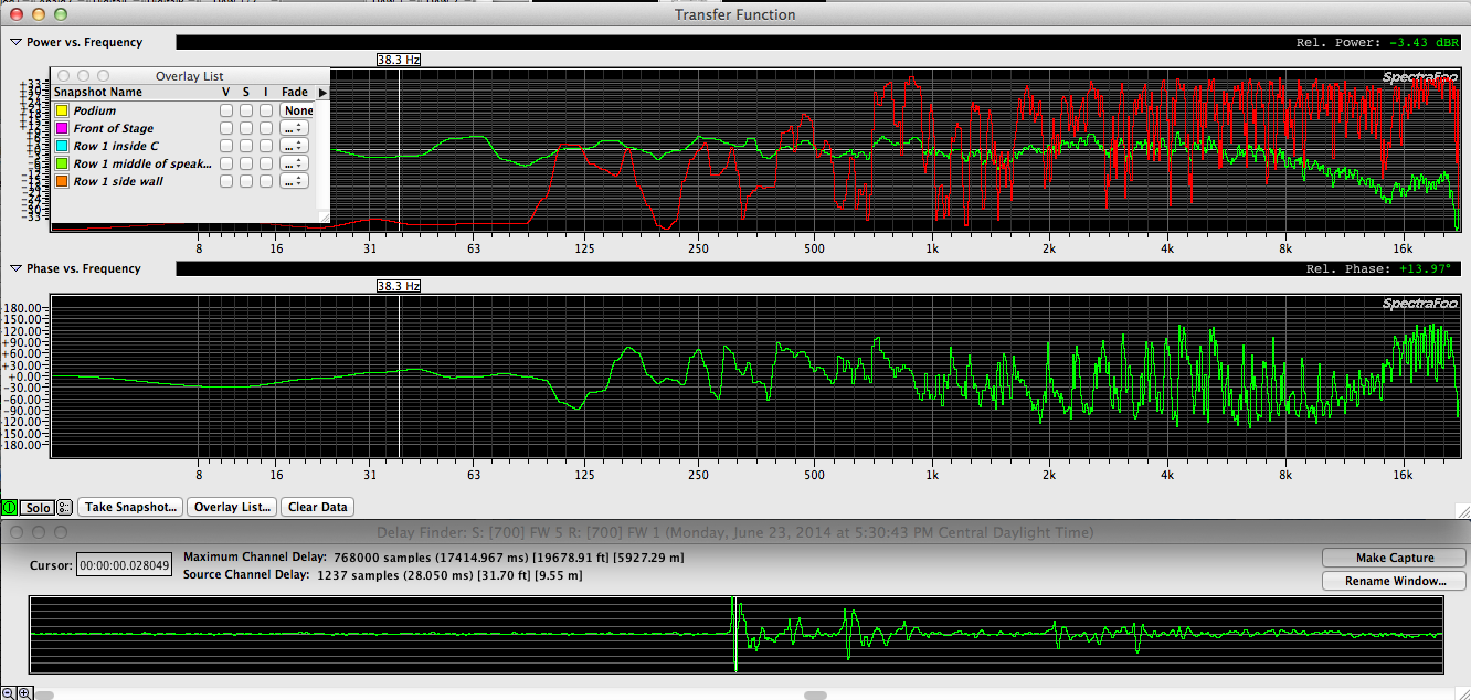
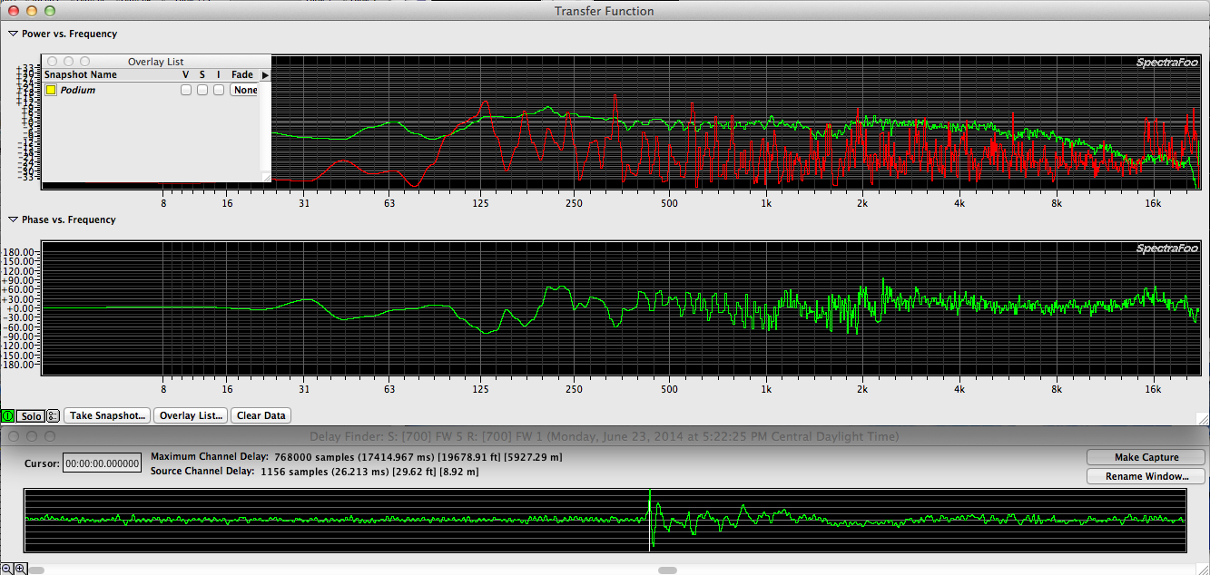
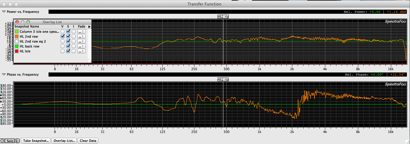
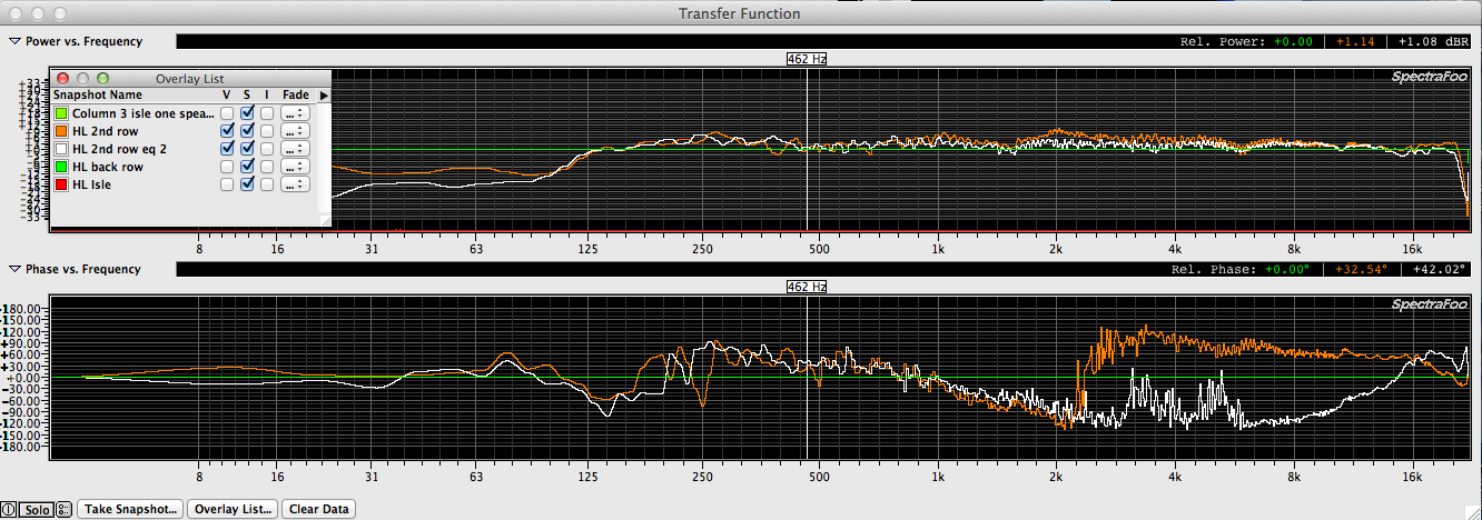
Here is the response of the single HL speaker at the second row position again with corrective EQ performed at the dbx driverack 260 (white trace). I would of addressed the extra bit of low mid energy around 250hz but the dbx Driverack 260 only allows for (4) parametric filters on the outputs & I had already used those to tame the extra high mid energy. I would of remeasured at the same middle & rear position as I was tuning but congregation members have already complained that it’s too loud up front & the cuts that were made at 7k, 4.5k, 2k & 1k will help solve that issue. Those sitting further back will have to suffer a bit until the delay speaker pair can be installed. In the meantime, everyone should benefit from unplugging the extra speakers.
Before & after EQ with the mic at the second row.
A recap. The extra pair of speakers are unplugged now & the system sounds & measures better than with (4) speakers improperly coupled.
The extra pair of speakers can be relocated 1/2 way back in the space to solve the loss of high frequencies due to distance from the mains. This will also allow for the main speakers to be turned down & also aimed down more which will help keep them from blowing on the back wall & side walls since they will be covering less.
Truly a win / win situation.
A few thoughts.
IF you need more coverage than one cabinet can provide, there is a right & wrong way to add a second cabinet.
1. The splay of the two cabinets need to be such that their coverage patterns overlap correctly. In an ideal situation you would use speakers that are designed specifically so that when the sides & fronts are touching, the coverage overlap is correct. One example of this type of speaker is the L’Acoustics L’Arc. The product like offers a spot & flood model. No matter how you mix & match them, their horn coverage pattern is the same as the outside cabinet angles so you get perfect overlap no matter how many of which cabinets you use. Smart!
If you don’t have the right type of cabinets but you need more coverage than a single cabinet provides, you need to do your own calculations. For example, if you have (2) cabinets with 80 degree conical horns (like the Toby Blasters), they should be splayed so that they are roughly 40 degrees apart from each other. Maybe a bit less, maybe a bit more. That is why we measure. To avoid guessing. At the same time you need to consider if having 110+ degrees of high frequency coverage is going to energize the walls and / or ceiling. If so, you might be better off with some coverage issues than with inherent phase issues that come with using a second cabinet. In the case of this church, small front fills would be the appropriate solution for covering the first row of seats.
2. If the cabinets you use aren’t designed to be perfectly coupled, you can still locate them side by side but in addition to setting the splay between the cabinets right, the delay offset between the two cabinets needs to be correctly set. Maybe one of those cabinets can be operated at a lower volume because it’s covering less & that alone will help minimize the bad stuff that can happen between adjacent cabinets.
3. Any time you couple full range cabinets together, you will see an addition in LF response of the system. Especially in the range where the cabinets become omni directional. This dictates that you should have a separate DSP & amp channel for each speaker. This way you can balance level, eq & delay to make the two cabinets working side by side as a complimentary pair.
It’s much easier to get (2) speakers widely spaced apart from each to sound good compared with (4) speakers coupled as adjacent pairs unless you have the right speakers or at least the right knowledge & gear. When you don’t have the tools to model an acoustic space prior to designing a PA, I would suggest that you experiment with only (2) speakers as a starting point & see what can be learned. If I’d spent enough time comparing (2) to (4) speakers in this space, I think I would of come to the same conclusion I reached today…Less is more.
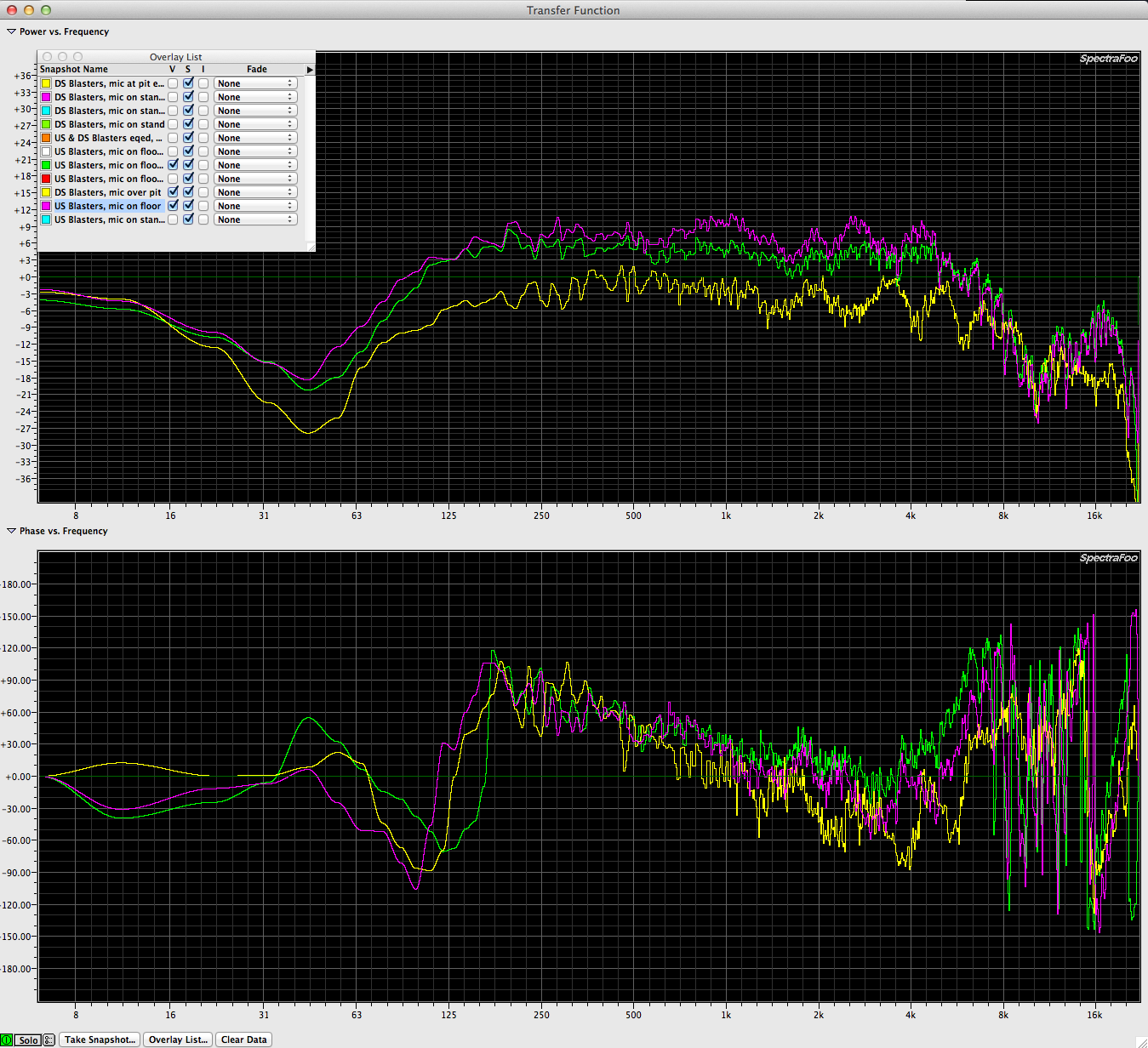
Overhead monitors – mic on a stand, mic on a floor, mic over the pit
When I work with Texas Ballet Theater we use stage monitors flown over the stage on batons. The TOBY speakers were designed specifically to fit perfectly between adjacent batons & are on yokes so they can be aimed downward & across the stage. The idea was to build a monitor that has the same profile as an ETC stage light. The one downside to the Toby “Blaster” is that is mechanically rolls off at around 100hz but since they’re always used in conjunction with a Main PA, this isn’t really a problem.
The stage monitors are flown instead of set on the floor to keep them out of the way & to make sure that dancers don’t stand in front of them blocking them for other dancers.
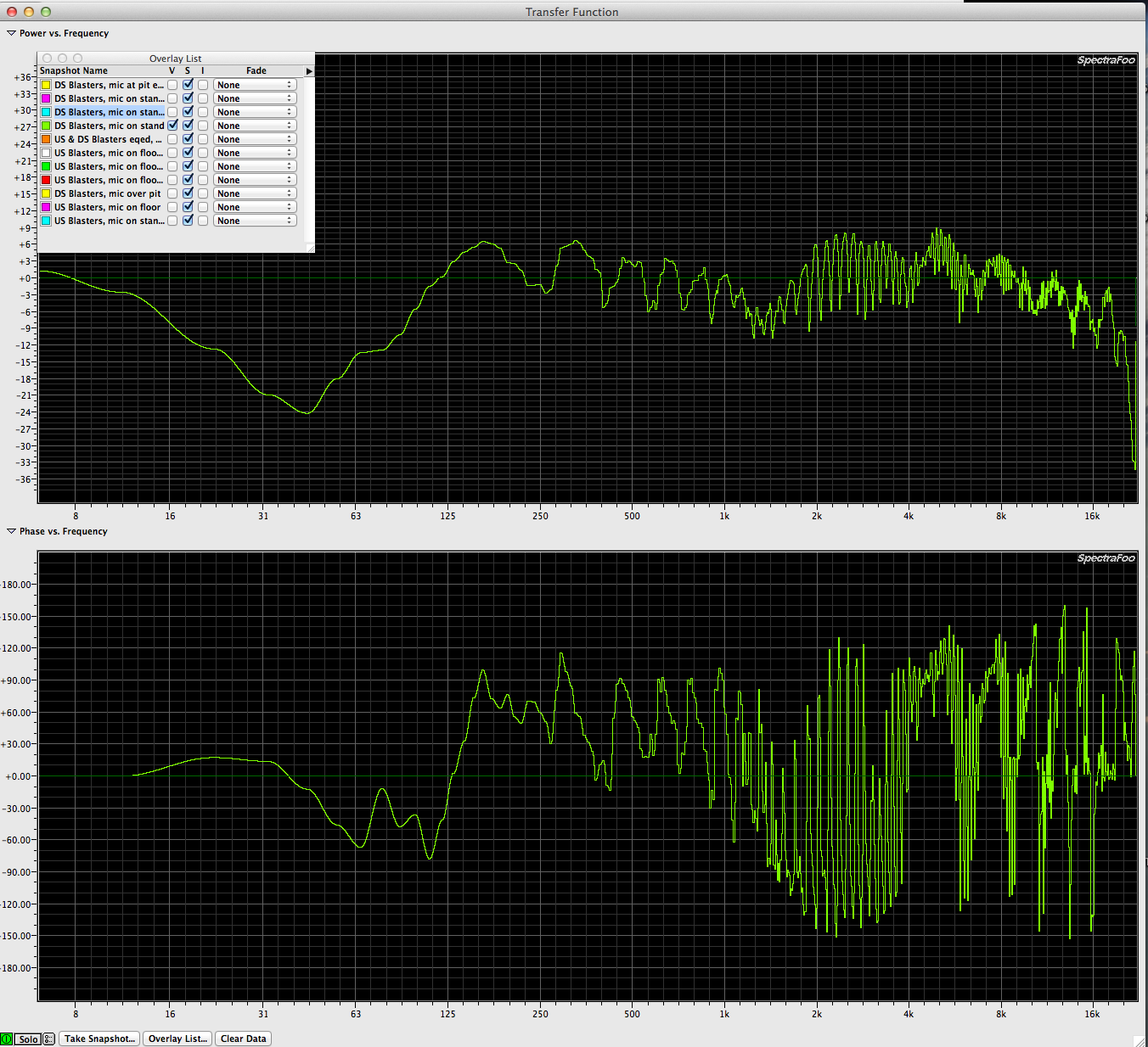
During a recent Swan Lake production I took some screenshots of my measurement graphs when I was performing corrective processing.
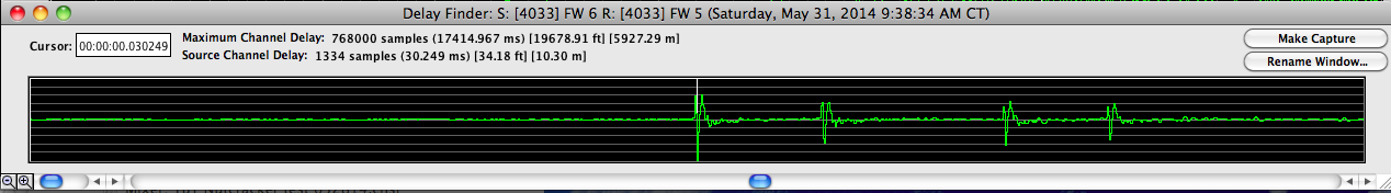
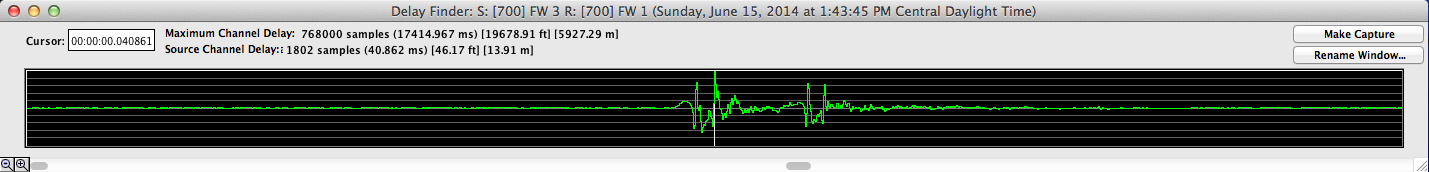
When you begin the measurement process, your first task is to set the delay correctly between the source & response so you’re phase window is presenting useful information. As you capture the delay time between the source & the response, you also get a graph of the theoretical impulse response of the system being measured. Your measurement app inserts a delay on which ever signal needs to be delayed to line the two signals back up.
In this case, there is (1) speaker and one mic.

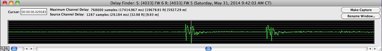
In this case, there are (2) speakers and one mic. The first transient is closer & louder. Both speakers are reproducing the same sound.
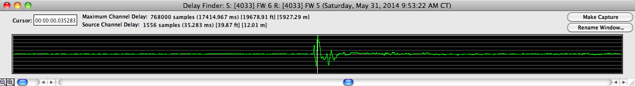
In this case, there are (4) speakers and one mic. The first transient is closer & louder. The other (3) speakers are reproducing the same sound but at a lower volume because they are farther away from the mic. If I went to the trouble to find the exact center of all the speakers, these separate transients would possibly become one. It would be fairly easy to achieve this with (2) speakers just by moving the measurement mic toward & away from one or the other speakers & based on a new impulse response measurement, narrowing the position. With (4) speakers, I’m not sure one would ever get there. This is why it’s important to measure single speakers if at all possible. Whether that means unplugging or muting at the DSP.


For this production there were (4) overhead monitor speakers. A pair downstage & a pair upstage. During the first performance, some of the musicians in the pit commented on hearing the stage monitors & what they described as feedback. I took this information as indication that the stage monitors were:
A. blowing into the pit (a mistake of placement on my part)
B. unbalanced in frequency response (a mistake on my part for not prioritizing tuning them before the first performance)
So what did my measurements reveal?
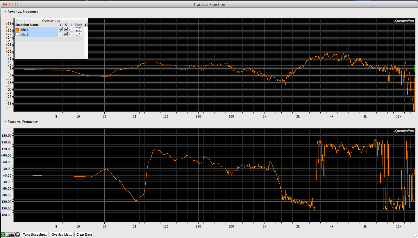
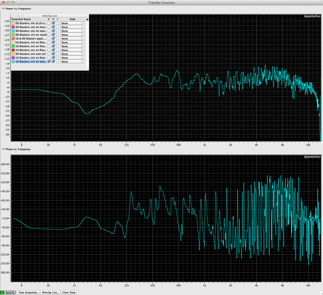
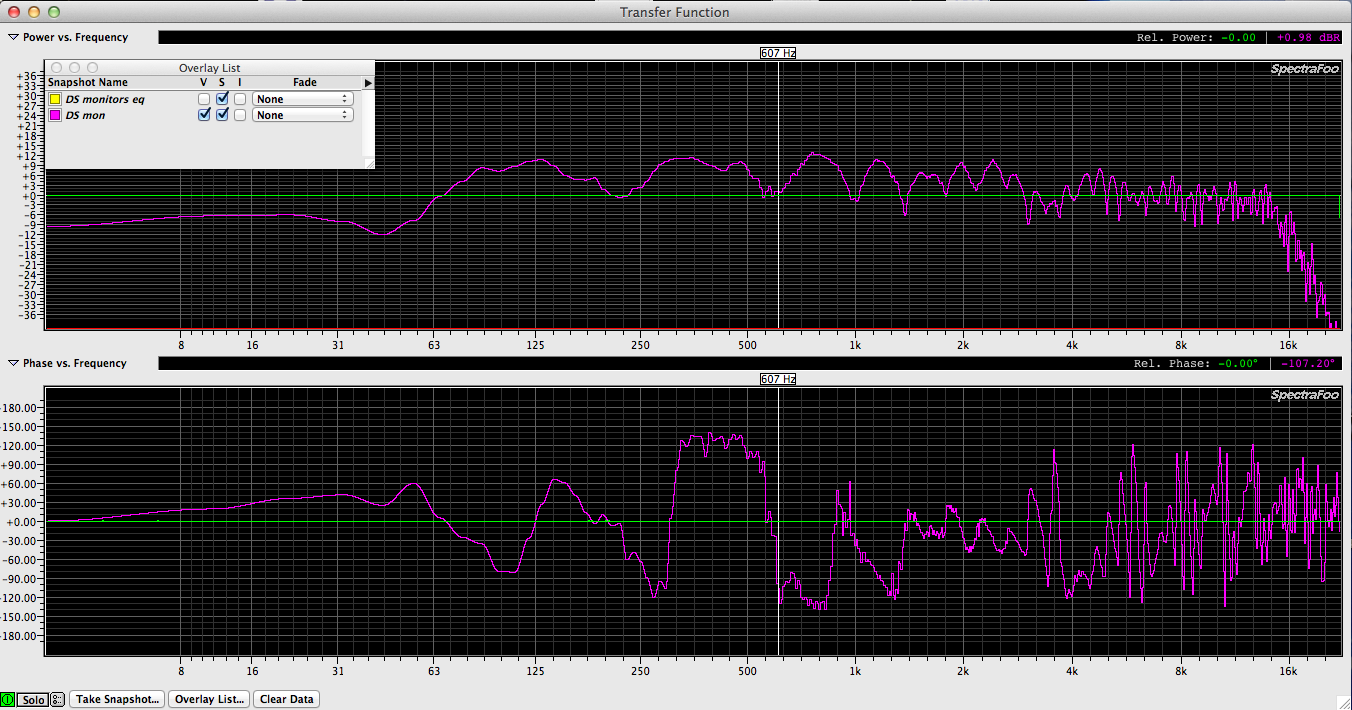
This is a measurement taking with the mic on a stand in between the downstage pair of speakers. Classic comb filtering & excessive low & high mid content.


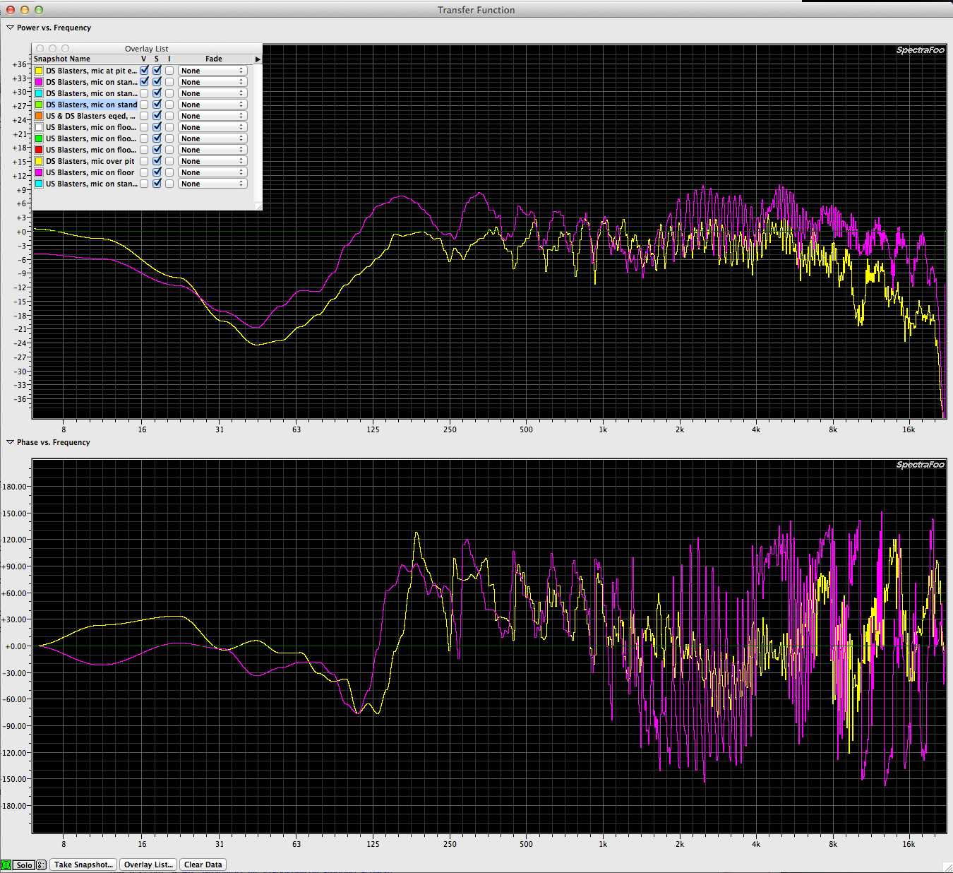
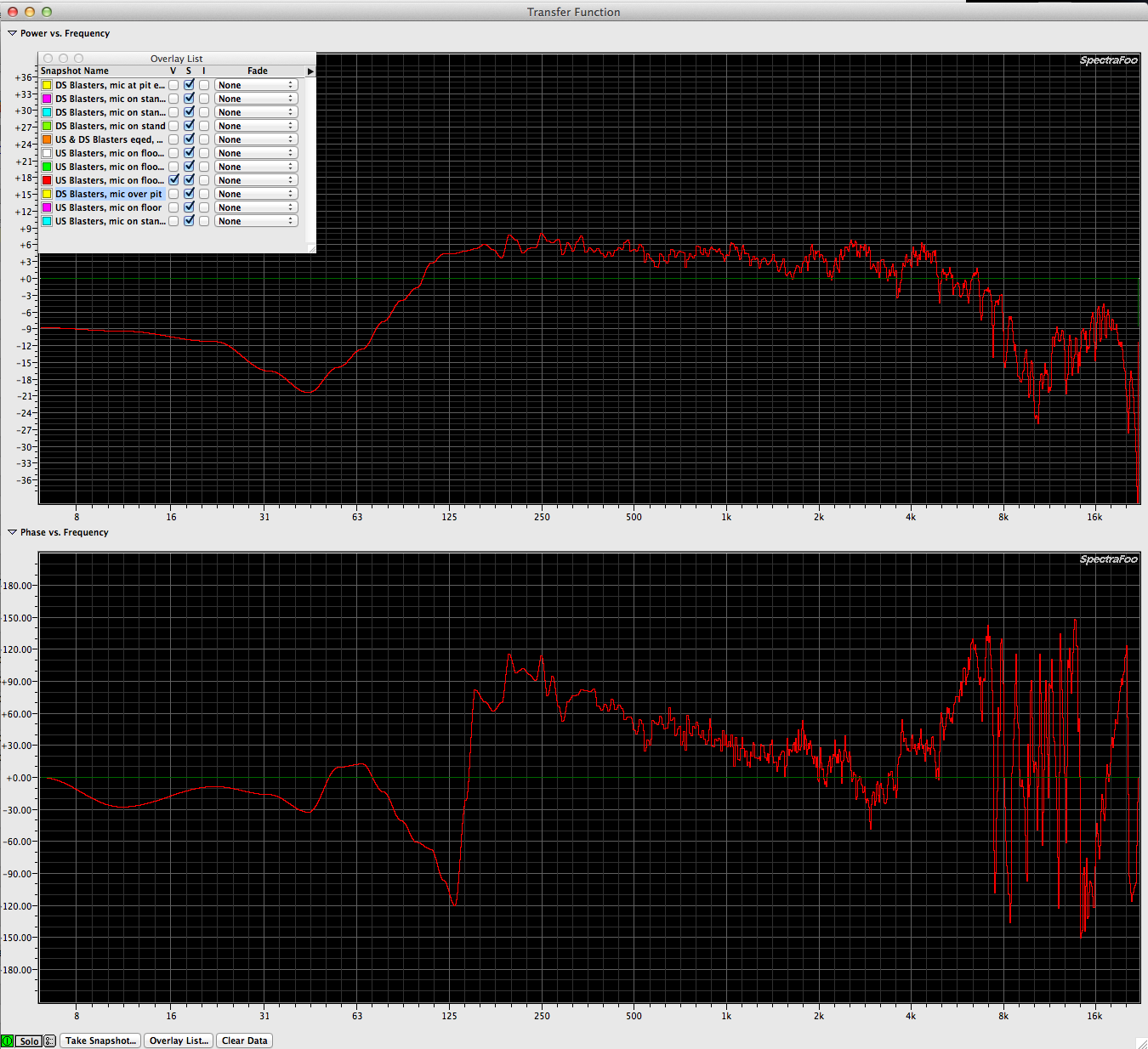
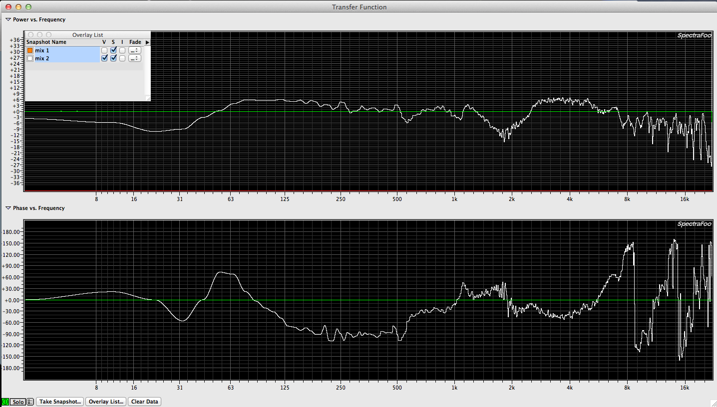
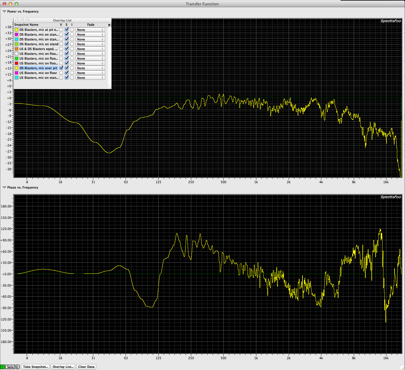
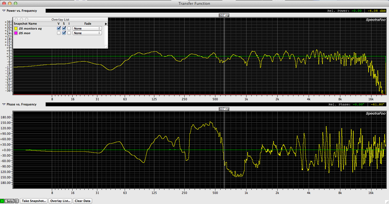
This is a measurement made of the downstage overhead pair after I performed corrective EQ with the mic placed over the pit. It shows that the highs are rolling off but the mid range is still quite present. The comb filtering caused by having (2) speakers cross firing is still visible.

crossfiring deck monitors
A common practice in live audio is to use a pair (or more) of speakers located in the wings to cover the stage for monitors. What is wrong with this? An better question is, “what isn’t wrong with this practice”?
The results of a recent measurement session at the Winspear Opera House for a dance production are a good example of how cross firing speakers interact causing massive comb filtering:
Comb filtering results from combing multiple signals (audio &/or acoustic) that are out of time. The amount of comb filtering & the frequency at which the filtering starts is determined by the amount of time offset.
The measurements also reveal how placing speakers near a boundary (the floor, a wall, the ceiling) creates excessive low & low mid frequency content which causes an unnatural balance for the performers & any audience members who are able to hear the stage monitors.
A speaker that measures flat when in free space will have extra low & low mid content when placed against or near a boundary. If a speaker / speakers is placed near multiple boundaries, the low / low mid content will be increased further. The same is true of mic position. think of mics & speakers as cousins that both have the same grand parents. Mics are small & capture sound. Speakers are large & reproduce sound. Both respond to the laws of physics in the same manner.
Measurement rig: Spectra Foo Complete
Mic: Earthworks TC30k
I/O: Metric Halo ULN2
Source: (2) Renkus Heinz two way self powered speakers (15″ woofer)
Ideally you want to measure speakers one at a time but for this purpose, I knew the speakers were going to be cross firing so I purposely measured both speakers at the same time from a central location.
So the first thing you always do is take a time measurement to let your measurement app figure which signal is early & which one is late. In this case I’m measuring the internal signal generator in Spectra Foo Complete again an Earthworks TC30K so obviously the signal from the mic will be last.
Here is what you get when you measurement (2) sources that aren’t time aligned (impossible with cross firing deck speakers). This graph is called an “impulse response”. It is a glimpse into the time domain. If there was only (1) speaker & there were no immediate boundaries to cause secondary reflections, you would see one excitation. Instead with (2) speakers cross firing & not evenly spaced, you see (2). If the mic were placed exactly between them, you would see a single excitation but it would be more pronounced.
Here is what the resultant response looks like. Note all the comb filtering (extreme dips) across the entire audio range.
That is caused by having (2) speakers out of time with each other firing at each other. A sort of worst case scenario. Of special interest is the excessive low & low mid information. Roughly 9db at the peaks between 63hz and 2.5khz. Trust me. You don’t want 9db of extra low and low mid energy on stage. That sort of spectral tilt at the state will easily overpower the mains for those up close to the stage.
This is a capture of how the response looked once we did some parametric eq correction. Note that the comb filter is still present. I knew going into this measurement that I was dealing with a poor acoustic condition that wouldn’t change. Some times you pick your battles & this time I was just hoping to reduce the LF build up on stage.
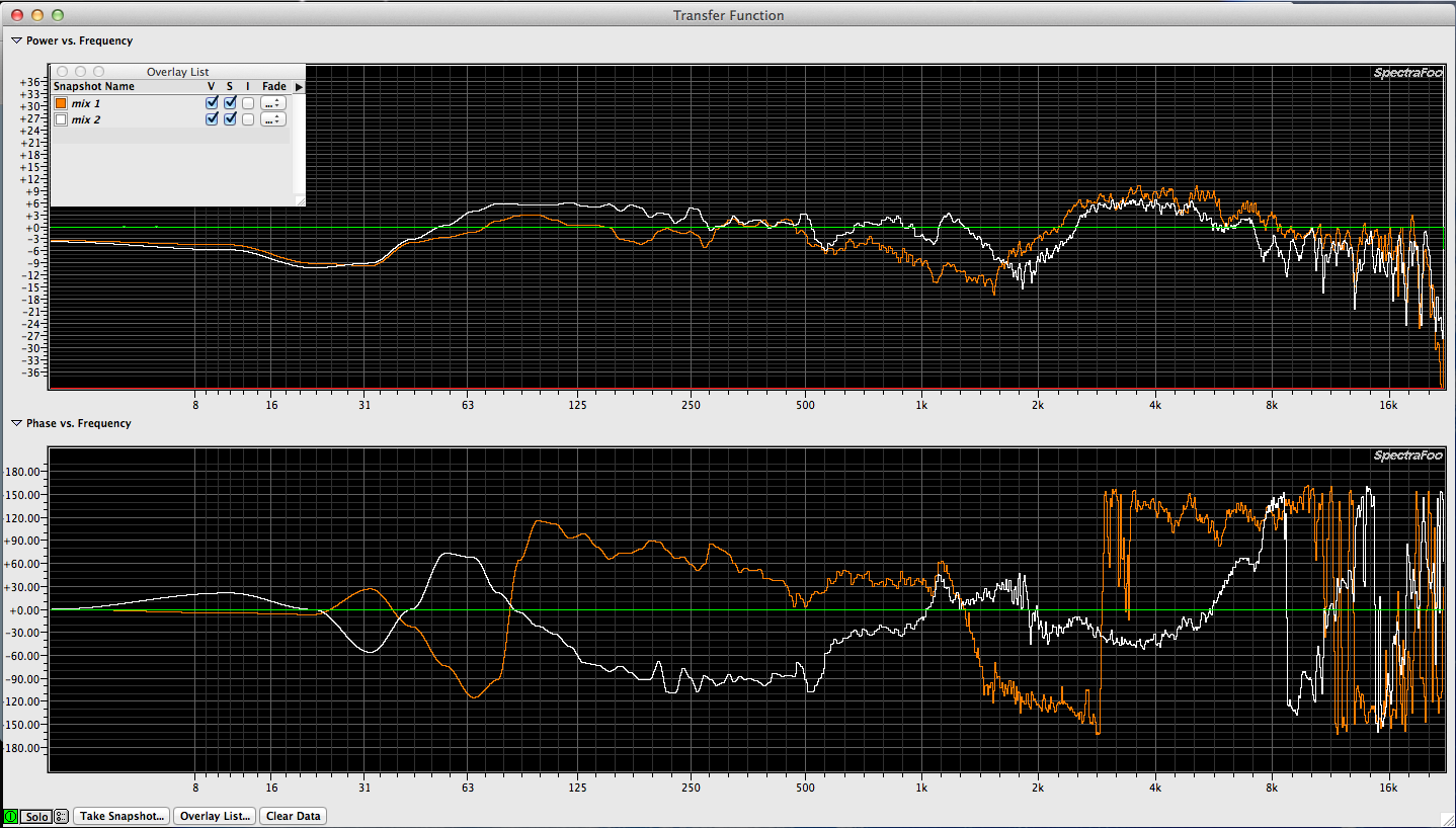
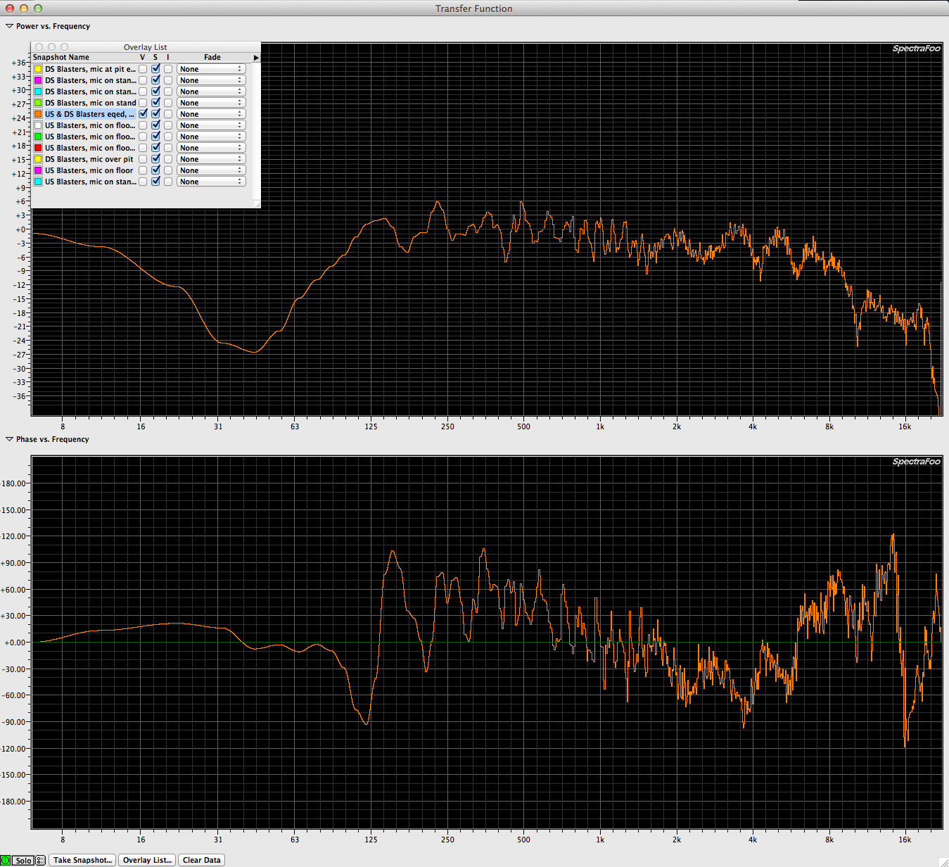
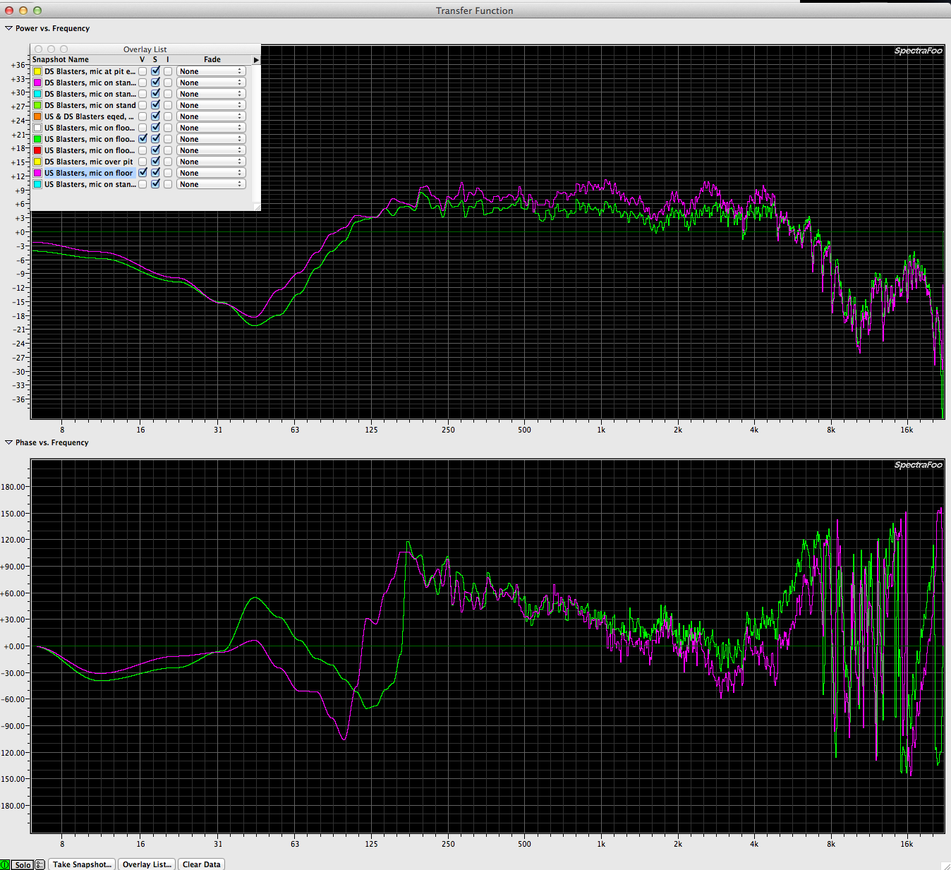
Overlay the two graphs & you get this:
After these measurements were made we copied the same eq & pasted it onto the upstage pair of speakers. In theory, turning on (4) speakers created more low and low mid content even though each pair of speakers was flattened out a bit but I didn’t get a chance to measure with all (4) speakers on at the same time. I know that they would of interacted with each other so the comb filtering would of been worse.
The moral of the story is that you want to avoid cross firing speakers when at all possible. By raising speakers off the floor you avoid excessive low / low mid build up. Anything to avoid (2) speakers aimed right at each other & outputting the same exact signal. But it’s a common practice to put speakers offstage firing at each other so it’s good to understand what to expect, what can be done to minimize the affects & to know when to take dinner…
SHOWCO – The Summer of 1992 with The Beach Boys and Ozzy
I had the good fortune of landing a job with SHOWCO in 1992. The shop was off Regal Row in Dallas. I showed up for work on my first day & a staff member (I don’t recall his name) took me around, introduced me to various department heads & then ushered me to my area. Cable. Cable for miles. My new job was to catch all types of cable as it came in the door from being on tour & test it & then put it back where it belonged. I showed up the next morning & the guy I’d met was gone out on the road. I was obviously “trained” and “qualified” in managements mind so I went back to work sorting & testing cable. A few days later a gentleman named John Blasutta came up to me & asked, “Do you have a passport?”, “yes sir!” I replied. “We’re going to Mexico…” he said.
I think we left about 2 weeks later so I got just enough time in the shop to get really excited. Billy Joel’s rig came back from the road while I was there. Chicago too maybe. A few tours were getting prepped while I was there to go back out. Lots of speaker testing in the area next to cable.
I did a very small tour of Mexico with SHOWCO & The Beach Boys in the Summer of 1994. I learned later that The Beach Boys was a sort of test site for new SHOWCO guys & I must of done OK since I was sent on to my next adventure.
OZZY – No More Tours Tour 1992
This gig would ultimately prove to be the end of my SHOWCO career. There must of been an unspoken rule that new (green) SHOWCO employees had to be broken down in spirit because I endured the equivalent of hazing by the monitor guy GUNK & then his assistant TATERS. I didn’t get hired because I knew everything there was to know about audio & touring. I got hired because I was a warm body, was inside the system and was eager and willing.
I was given the nickname “EB” by GUNK soon after my arrival at the rehearsal complex, a reference to the “Green Acres” character & it caught on. Soon the whole crew was calling me that…
http://en.wikipedia.org/wiki/Tom_Lester
At the time I was making $600 a week & doing 4 or 5 shows on average per week & show days were as long as 18 hours each. You do the math. Come to find out later that SHOWCO charged $1500 a week for my services.
I’ll save the gory details but the tour was due a short pause & Sharon (Ozzy’s wife) became ill so he canceled the next leg of the tour. I went back home & worked a bit more at SHOWCO in the shop but soon that was over. I don’t even recall what happened. I was just glad to be away from GUNK & TATERs. While there were a lot of bad things about that tour, I still learned a lot of important things. How to work without sleep, how to skip meals, how to get yelled over the PA in front of a packed arena, etc… Good stuff that prepared me for my next job:)
What a long & winded way of introducing visitors to the SHOWCO PRISM system.
At the time I toured with SHOWCO, the Prism rig was considered to be the Cadillac of speakers ans was shrouded in secrecy. Only once did I have one of the grills off. To take it off you needed a special oval shaped bit to match the oval shaped heads on the grill screws. I was told, “Go in that room, lock the door and remove the screws with this drill. Once the grill is loose, call me. I called and I left the room and the other SHOWCO tech went in and locked the door.
I’m going to see if I can find some information about the Prism rig now that it’s long since been discontinued and replaced by newer options never to return to the prime time slot it was once awarded.
More soon…
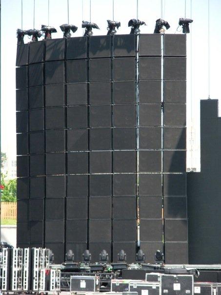
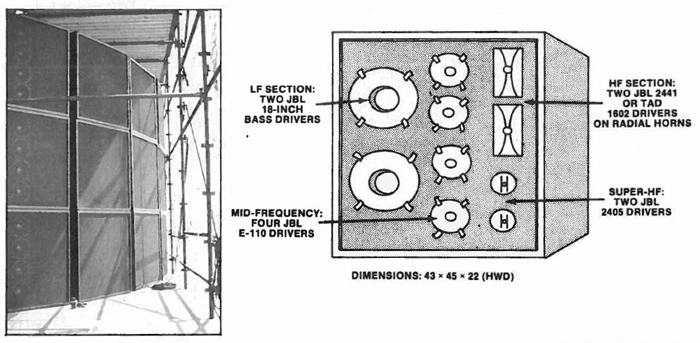
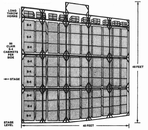
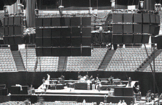
Clair Brothers S4 System
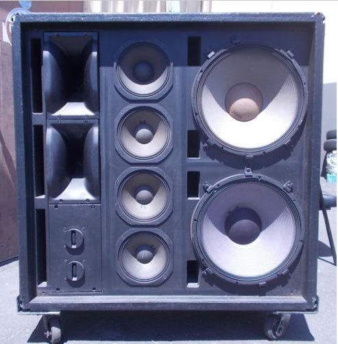
Clair Brothers S4
The Clair Brothers S4 cabinet is one of the few speaker cabinets that has passed the test of time. The S4 made a huge impact on the live audio industry when it came out in 1974! Here is a photo of one listed on EBAY recently that compelled me to find out more about the cabinet and it’s history.
A 3 part article about Clair Brothers on prosoundweb.com that mentions the S4 on part 3:
The Genesis Of Clair Bros To Today – part 1
The Genesis Of Clair Bros To Today – part 2
The Genesis Of Clair Bros To Today – part 3
QUOTE:
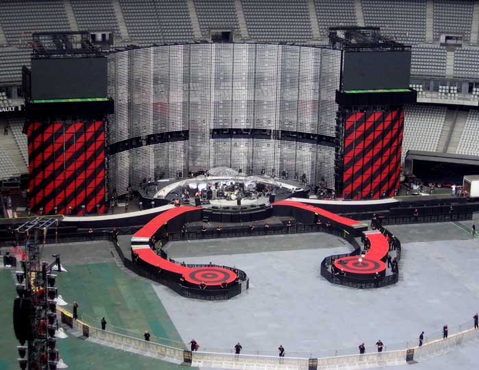
“In 1974, a large leap forward was made by the company with the creation of its S4, single-box loudspeaker system (the first all-in-one four-way box), with its hanging grid system. Previewed on Rod Stewart’s tour that year, the S4 created industry buzz, to the point that when Mick Jagger came to Stewart’s show, Clair Brothers was hired for the Rolling Stones 1975 tour after he heard the system.
The Clair Brothers S4 rig.
The S4 included high frequency drivers from JBL (2 x 18-inch, 4 x 10-inch, 2 x 2-inch, and 2 x 2405). Truck dimensions played an important role in the sizing of the S4, to allow them to fit two across in a standard trailer.
The S4 lasted more than 36 years, with updates as needed. The loudspeakers were even used in 2008 for the closing of the NY Mets stadium in New York City.”
——————————————————-
Here are some images from the internet.
I just spoke with an engineer who recently mixed a show on an S4 rig. How did it sound? “Good!” he said.
Why Measure
An industry heavyweight working with a top tier artist once stated, “I’ve been all over the world & I find something wrong with every sound system I measure”.
In the live sound reinforcement realm, many of us are faced with the daunting task of using an unfamiliar sound system in an unfamiliar venue for a career. The only way to know whether the rig is designed, installed & tuned well is to measure the components ourselves upon arrival. This goal requires that we schedule the time & commit to efficiently taking the measurements & knowing what to do once we have the facts in front of us. Is there time to fix things? Do we have the tools necessary to correct any issues we might find? Was the system brought in for this one show & we will be starting from scratch? Lots of possible scenarios.
Let’s be practical & logical since that is what audio people do. There is no good excuse to be an audio engineer that doesn’t know how to use the tools & take the measurements anymore. It’s mandatory in my view. The tools are inexpensive & the techniques are documented. Even if it takes years, we’ll all be better off if even the small fish in the pond starts the journey. We’ll all be better off when everyone understands how to measure correctly & what to do with the data.
In the studio or shop, being able to verify proper function of system components is vital when you rely on your gear to earn a living. Microphones get dropped. Speakers develop mechanical defects. Audio gear drifts out of spec. Gear malfunctions. Cables get build incorrectly. All these issues can be easily tested for & diagnosed with a basic measurement rig.
In the year 2014, we should have the tools and skills needed to verify proper function of any component in a sound system or studio environment. We should be able to quickly measure & verify whether or not a sound system is properly spec-ed & installed in a given venue. Hope is not an acceptable substitute.
This is why this site exists. To help audio engineers & system designers that don’t yet know all there is to know about audio measurements & sound system design & optimization learn how to measure correctly, take the results & know what to do with them.
The forefathers of this field thought that it would be months before audio measurement tools & the principles learned by measuring became common. Sadly, I don’t think we’re there even today as much of the time, my measurement rig is the only one in the venue & yet I’m not the system tech. There IS a light at the end of the tunnel though & I think it’s a laptop running measurement software lighting up the face of a diligent audio engineer who yearns to learn the truth & provide the coming audience with a pleasing sonic experience 🙂
common FFT mistakes
Here are a few common mistakes users make. Maybe by reading over them, you can avoid making the same mistakes:
1. forgetting to configure the rig to measure the desired speaker with the desired mic
2. forgetting to configure the PA so that only one speaker is producing sound for the measurement
3. forgetting to compute delay time prior to beginning the measurement process
4. forgetting to move the mic when taking the next measurement
5. forgetting to capture a measurement before moving onto the next measurement position