Speaker Design and Testing – books

I have been refurbishing a pair of Renkus Heinz TRC151/9 speakers for a local venue and during the process have realized that in order to understand, design and optimize a sound system (made up of individual speakers), one must understand how a speaker works, why it is designed the way it is and how to understand what goes wrong and how to resolve it. One could assume that for an installation involving new speakers, they would all be functional but this would be a dangerous assumption. Certainly if you’re dealing with a system that is older, there may have been many opportunities for something to be done wrong. For example, something as simple as replacing a blown driver may lead to the replacement driver being reinstalled out of polarity. “Isn’t red the positive wire?” Maybe. “Isn’t the red terminal on a driver positive?” Maybe. Obviously we can’t leave it to chance that a system is properly configured. We must verify each part if we are to know that we are making things better and not just spinning our wheels.

How does one learn about speakers, speaker design, speaker testing?

Some books I have come across that seem worth having in your library are as follows:

Loudspeaker Design Cookbook 7th Edition – Vance Dickason
Testing Loudspeakers – Joseph D’Appolito

As I have been trying to verify that the TRC151 pair that I have are back to factory spec, I have realized that some times the measurement results for even a single cabinet as simple as a two way passive design can be overwhelming. What do you do when the measurement is cut and dry?

Ask questions. I’ve written Eminence to verify terminal polarity on the HF driver. I’ve written Renkus Heinz engineers to verify expected results.

I’m about to email McCauley Sound who provided the 15″ woofer for the Renkus Heinz TRC151/9 enclosure.

More soon.

Recreating an analog EQ setting in a digital plugin

Last night during a ballet tech rehearsal I was asked to do some channel strip EQ on the Midas Venice 240 console. Knowing that the new EQ setting was appropriate for one of the 3 pieces of music, I set out this morning to measure the channel strip settings so that I could process the actual audio in Twisted Wave so that I could bypass the channel strip eq. With an FFT rig like Smaart, Spectrafoo Complete, etc…the process is accurate and doesn’t take much to achieve.

For the purpose, I used my Metric Halo ULN2 (2 channel audio interface). I used output 1 to feed a channel input on the console. I used ULN2 – output 2 to send pink noise out of the ULN2 and back into the ULN2 via input 2 (a loop). I took the direct out of the console channel and returned it to ULN2 – input 1. This setup allows me to measure only the console channel strip which is the simplest signal path to measure the channel eq.

INSERT photo of channel strip and the results from measuring…

Meyer Sound SIM3 or Rational Acoustics Smaart 7 class???

I had planned on attending both Meyer Sound’s SIM3 / System Design course with Bob McCarthy and Rational Acoustic’s Smaart 7 course with Harry Brill Jr this year in Fort Worth Texas but it just so happens that the classes overlap… 🙁

Meyer Sound – SIM3 Training and System Design with Bob McCarthy

Meyer Sound - SIM3 / System Design with Bob McCarthy

Rational Acoustics – Smaart 7 class with Harry Brill Jr

Rational Acoustics Smaart 7 with Harry Brill Jr

Considering that much of my lagging questions related to system design more than using the tools themselves, I’ve opted for Bob’s class this time. Smaart 7 training is at the top of the list though. I may have to get on a plane to scratch it off my list…

Saint Andrew – part 3

Finally getting back to this project…

I’ve spent countless hours thinking about this project, drawing pictures, measuring angles, asking my mentors questions, etc…

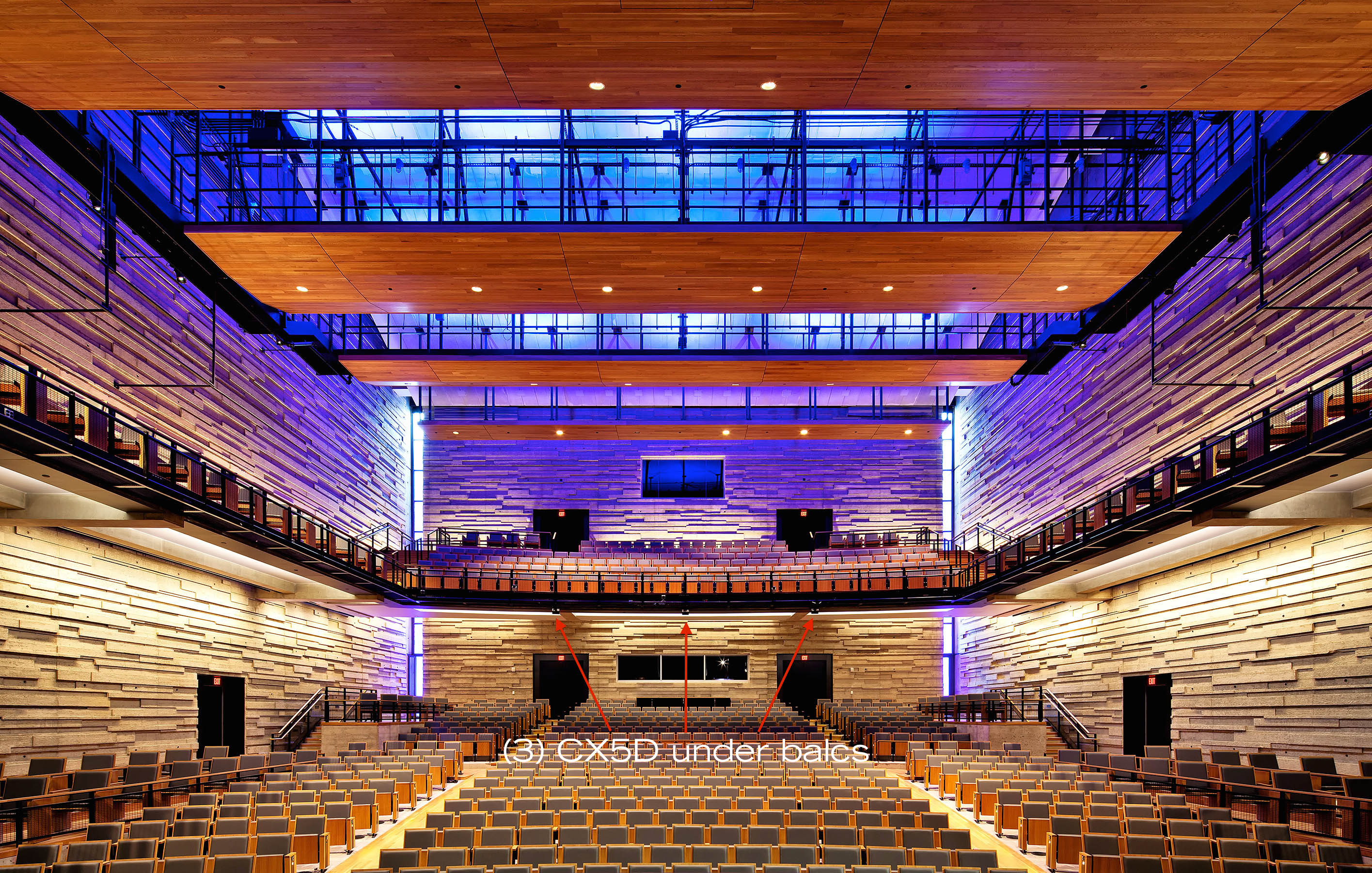
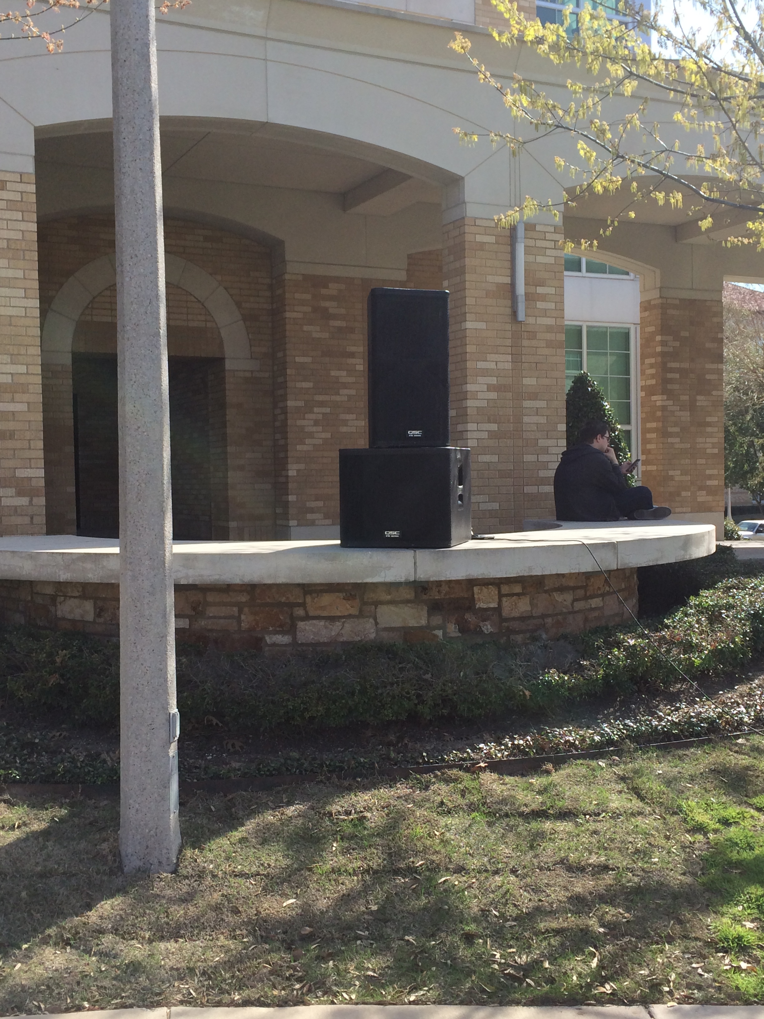
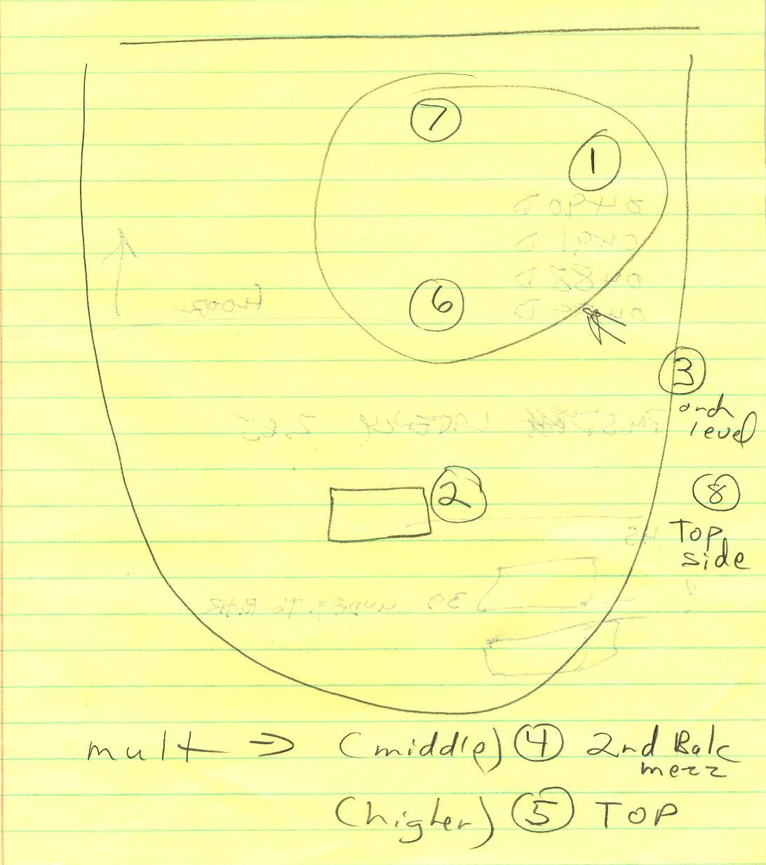
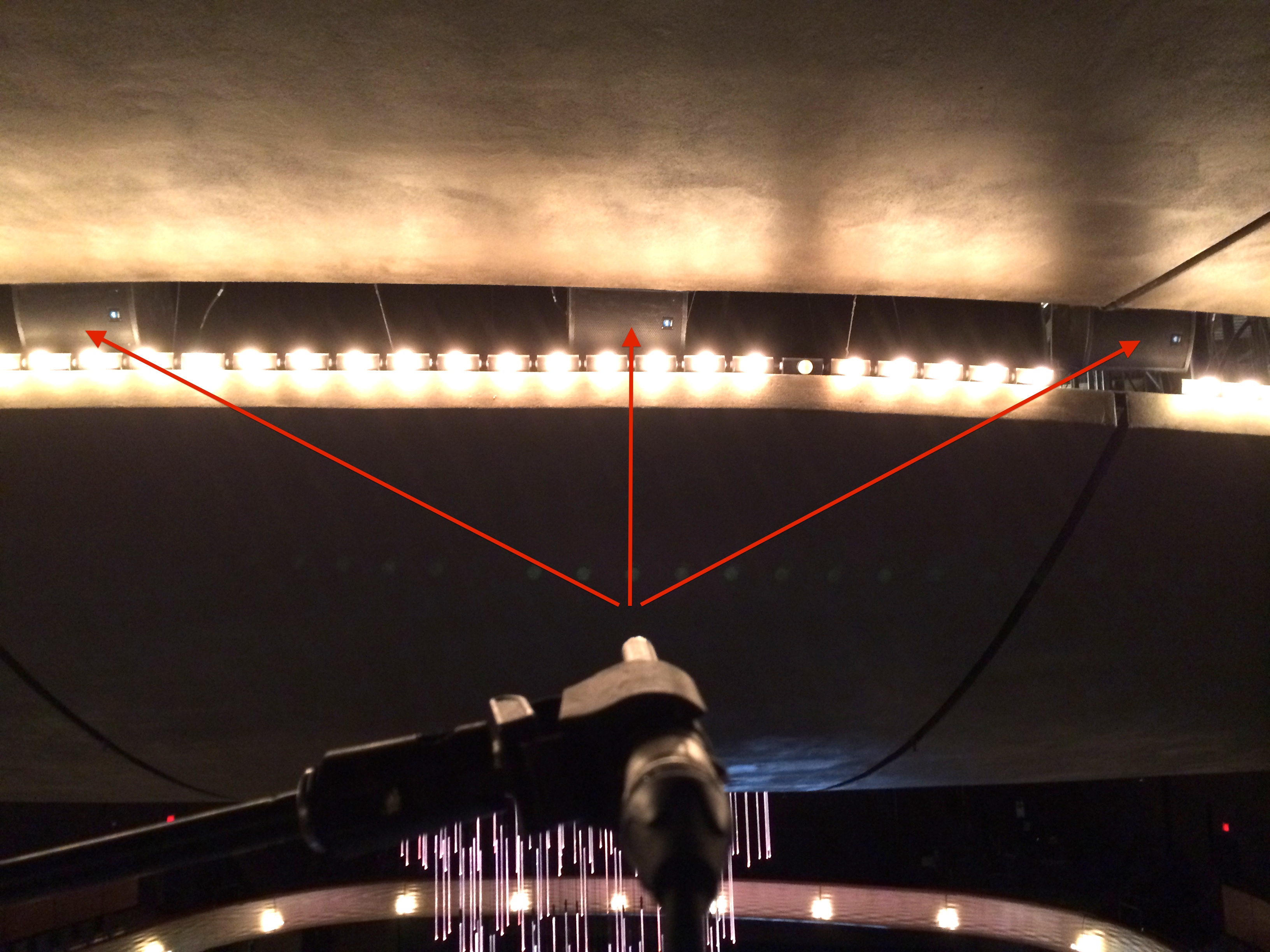
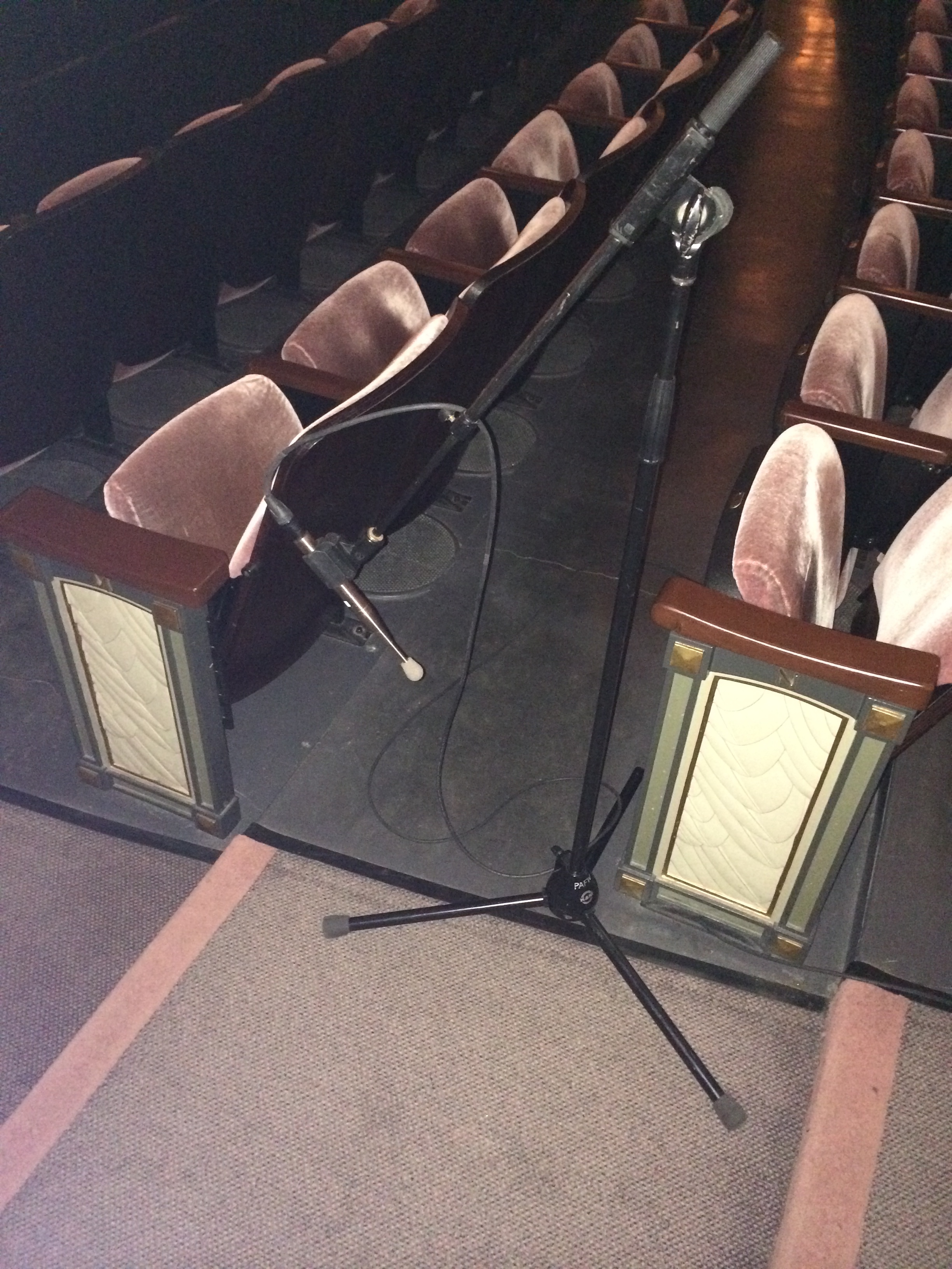
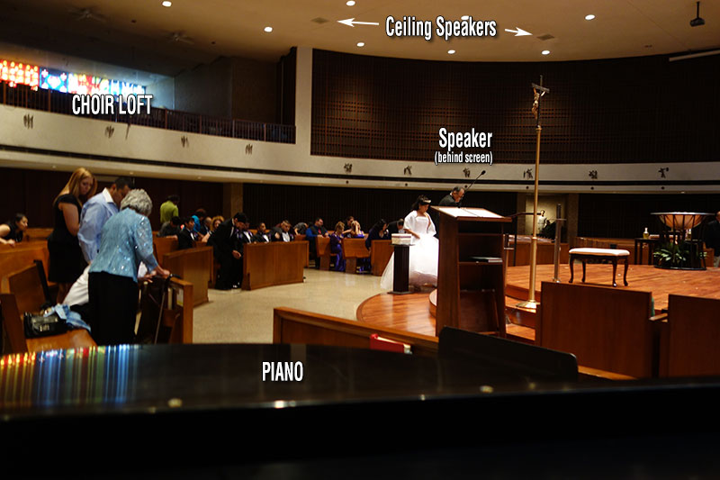
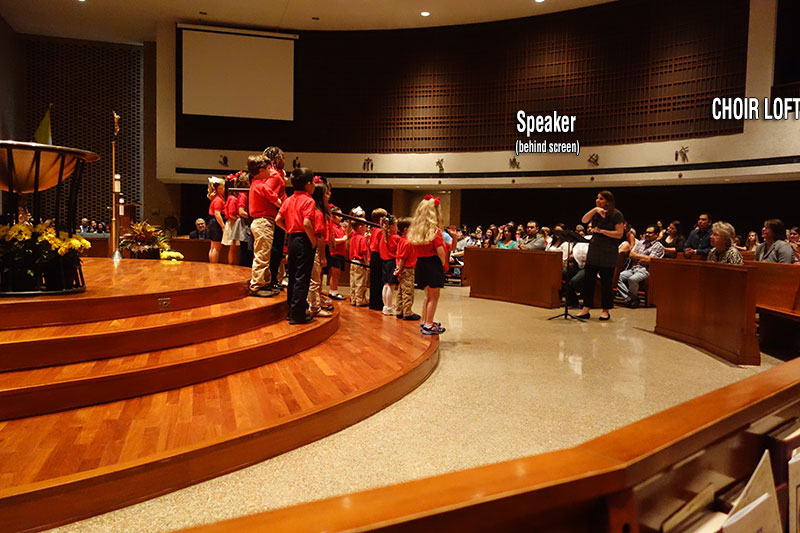
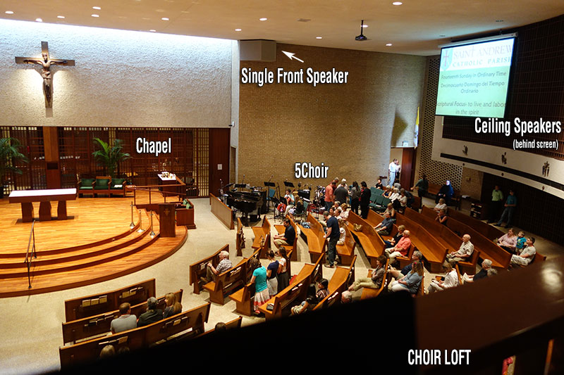
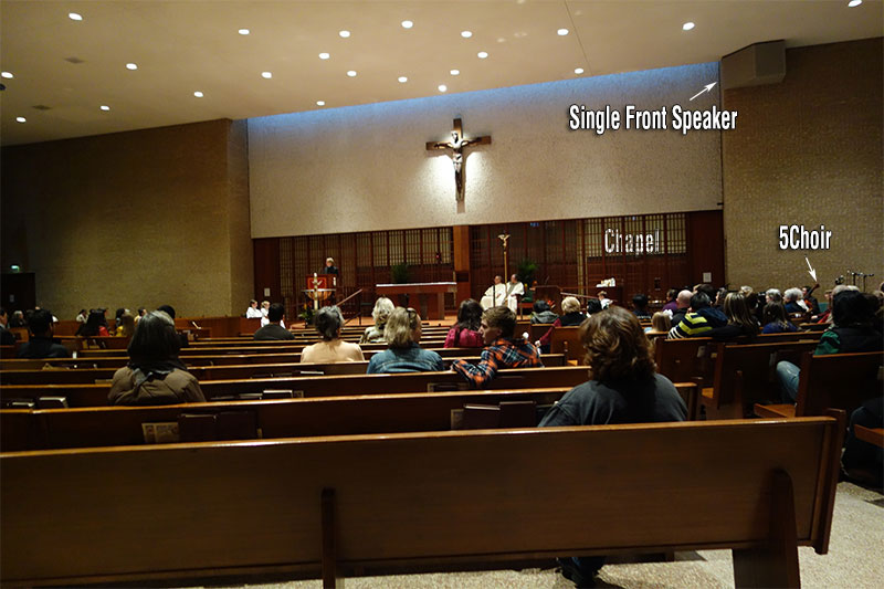
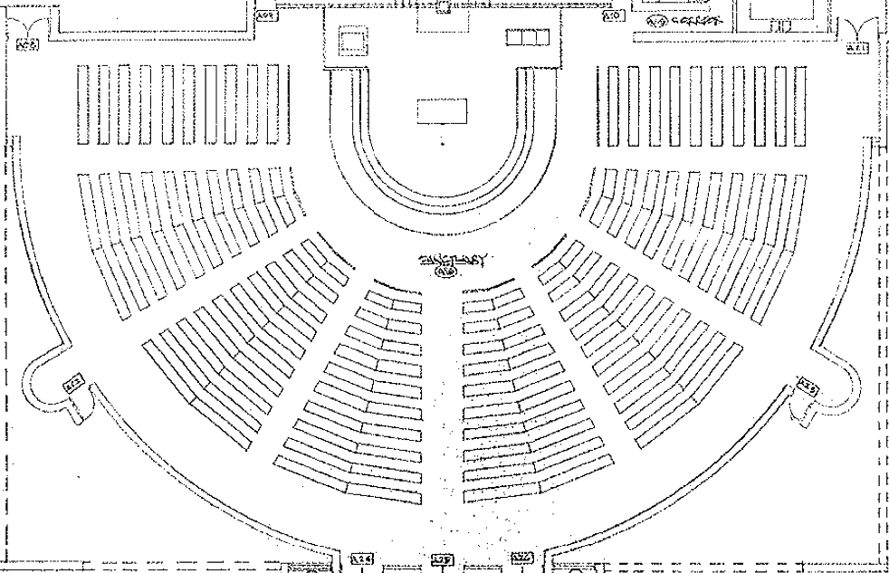
At the end of the day, there is no such thing as a perfect sound system design. Any system is a compromise so the goal is to optimize the system so that everyone has even volume and even frequency response without comb filtering and while trying to avoid exciting the room. This room is stone, wood, concrete, glass and plaster. Obviously we want to avoid exciting the reflective surfaces or intelligibility will suffer. As it is, just an un amplified voice in the room is already very wet. There may ultimately need to be some acoustic treatment in order to resolve some of the existing reflections. For now we will focus on deciding where speakers go, how many there will be and how they will be aimed. There are (8) seating areas. If that were the final statement, things would be easier to tackle but one of the (8) seating areas is sometimes used for the live band which means that the coverage needs for that last section of seating needs to be adjustable.

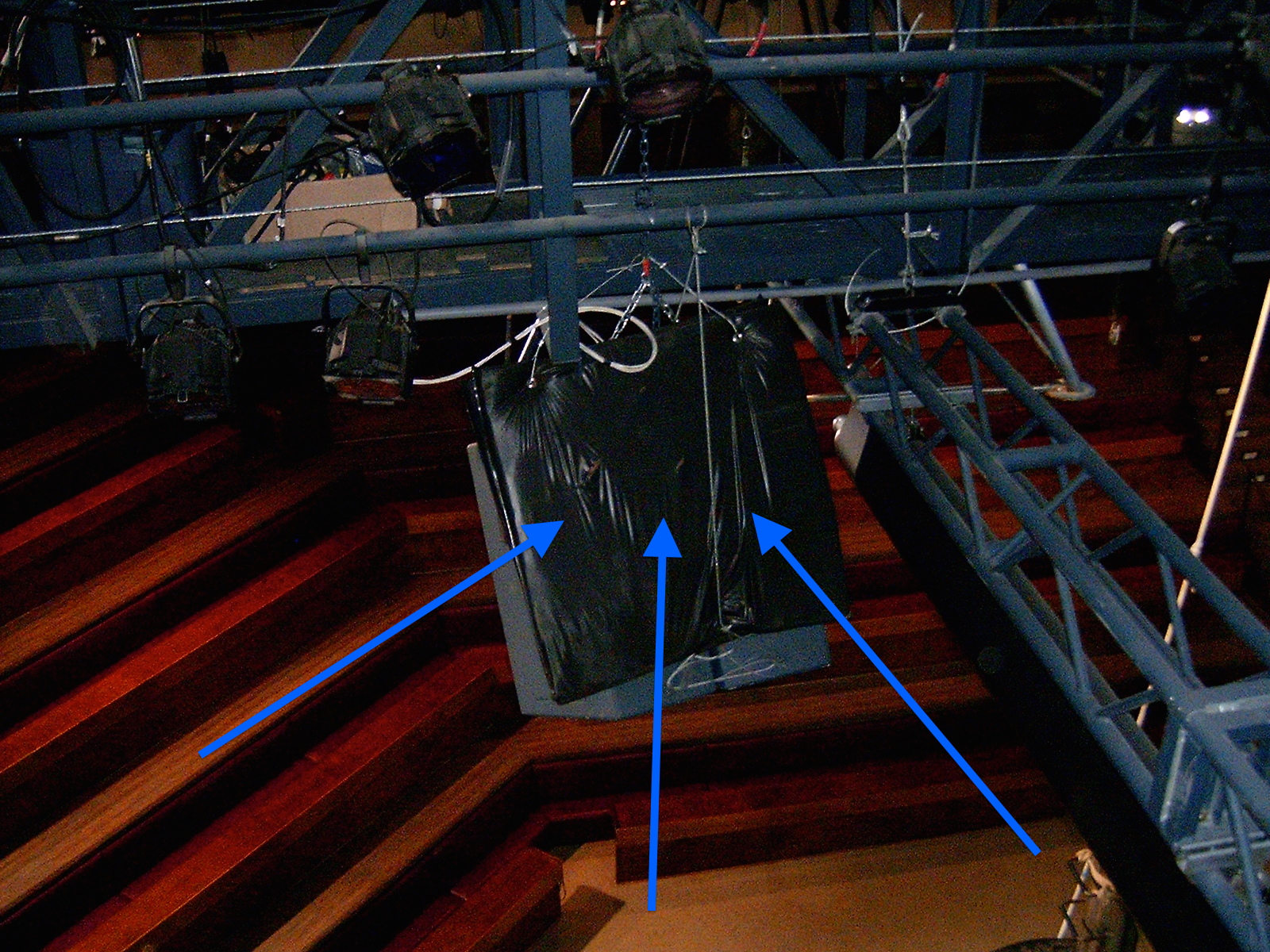
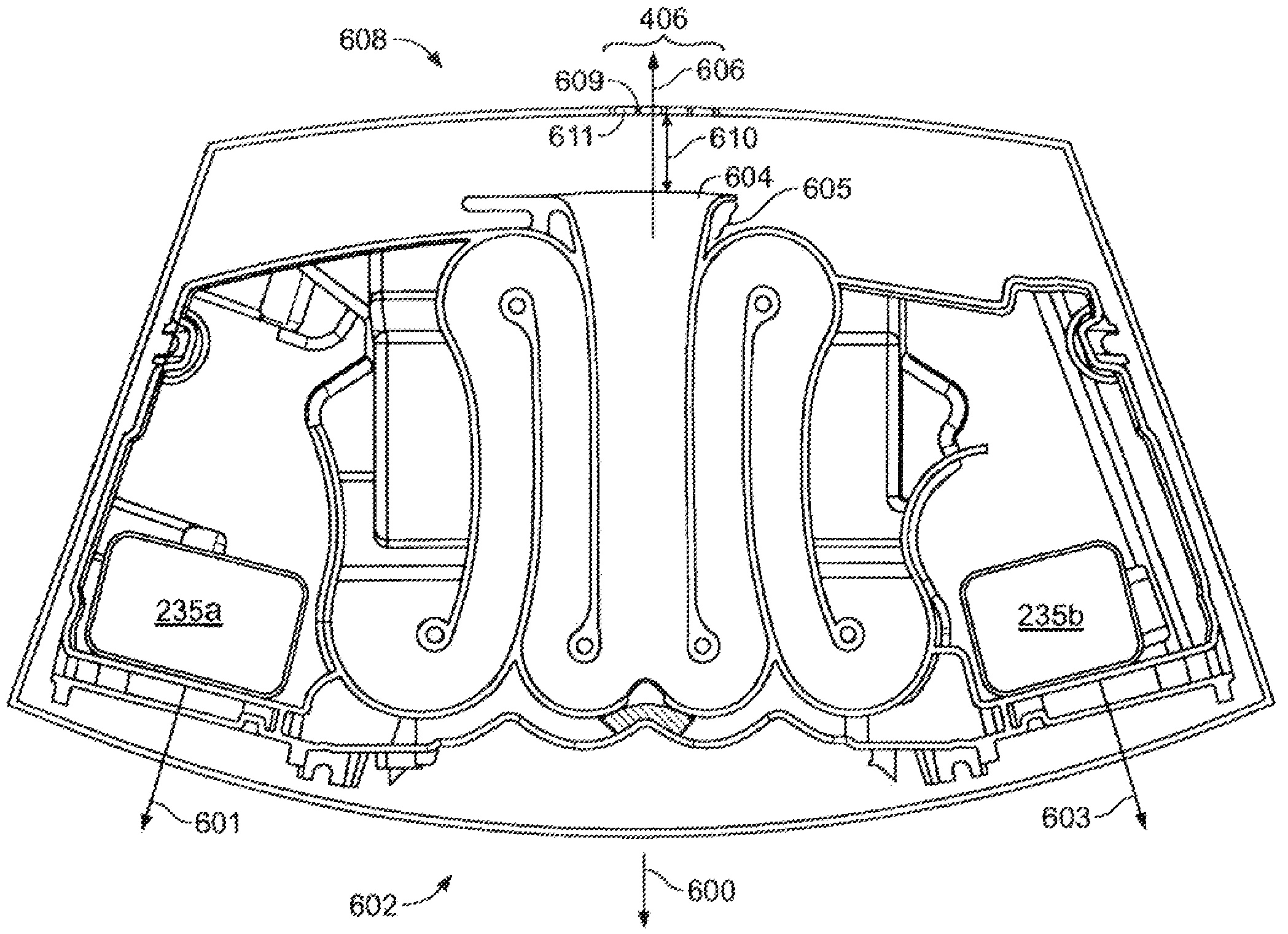
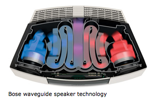
In a perfect world I guess we would use (8) speakers that could cover only (1) seating section but I’m not sure a speaker exists that has that HF dispersion pattern. Like this:

St-Andrew-top-view take 3 rev 3

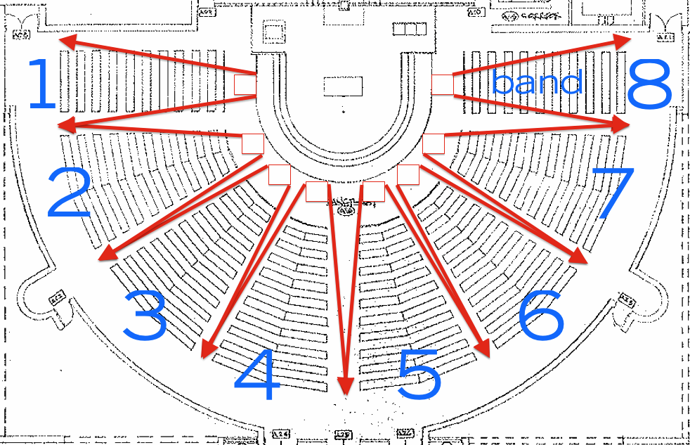
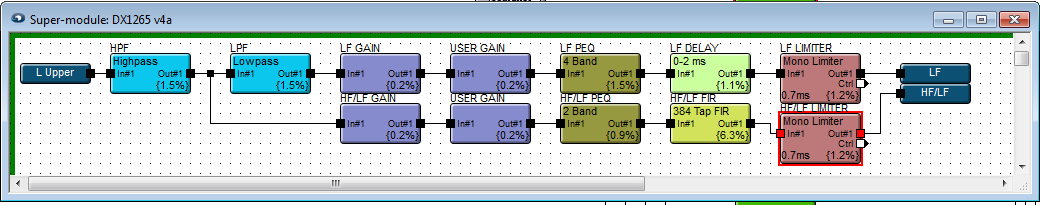
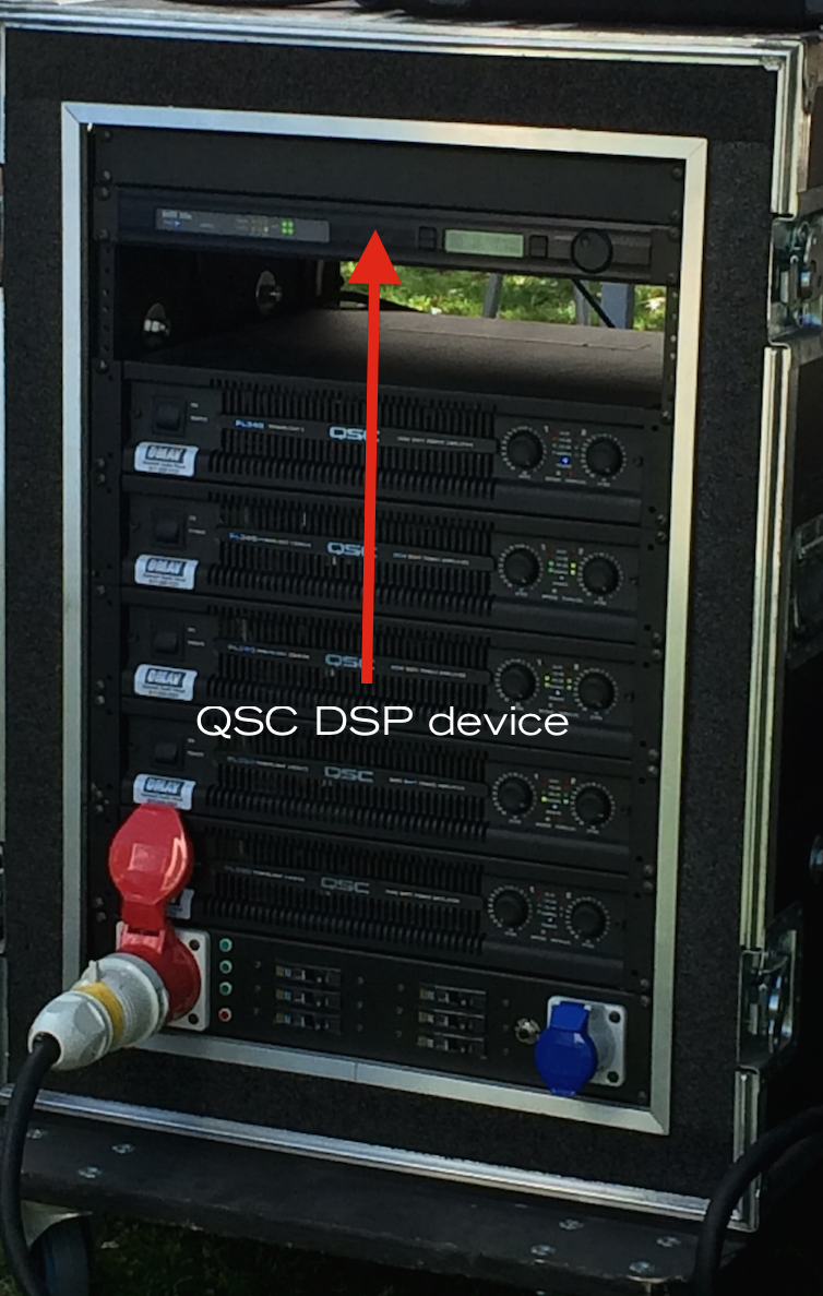
If we could find and afford a speaker that could cover only one section of seating and it was within budget to get (8) of them, we could mute the speaker covering the band when the band is playing and all would be good. Obviously using (8) speakers is more expensive than (6), (4), (3), (2) or (1). To be able to time align and eq each speaker there has to be an amp channel and signal processing channel for each speaker. That means each time we add another speaker to the design we add additional cost for another amplifier channel and signal processing channel. At this point I’ll mention that DSP (digital signal processors) typically come in 2input x 6 output or 4 input x 8 output or 8 input x 8 output. What this means is that once you go past the 8 channel boundary, you have to get another unit. At a minimum, this system will need an 8 x 8 DSP unit. Can the system be designed to work well with only (8) speakers total? Doubtful but maybe.

One of the goals of this system is to be able to reproduce full range sound (not currently possible) so there will be ceiling mounted subs involved. That will again require more amp channels and more signal processing. I like to avoid making hard decisions in the design stage because it limits creativity and also is unnecessary, until certain landmarks are reached, I’ll keep this design in the “theoretical” arena.

As a case study, I have made some speaker configuration options without concern of whether it physically possible or not. Unfortunately speakers don’t come in unlimited dispersion pattern options. Most speakers are designed for the masses so unless you spend a lot of money, you can expect to get speakers that have HF horns with 75,80,90,100, 105 conical patterns. If you need an asymmetrical horn, the options are also limited. Since the goal is to minimize the amount of overlap at the acoustic seam between speakers, you can’t just throw up any speakers and call it good. You need to make sure that you have chosen the right speakers for the necessary coverage but avoid excessive overlap. 5 to 10 percent is considered acceptable. More than that and you end up with severe comb filtering at the seem.

Meyer Sound makes some speakers with narrow horns.

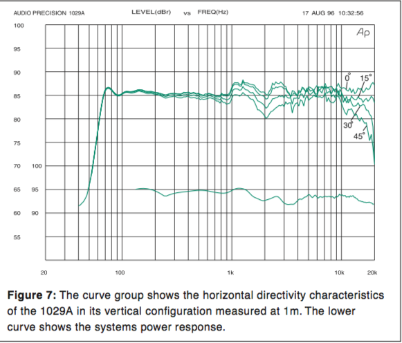
For example, the UPA-2P is has a 45 degree conical HF horn.
Meyer Sound – UPA-2P

Another example is the Meyer Sound UPQ-2P
Meyer Sound – UPQ-2P

Either of these might be an appropriate speaker choice for covering (8) separate seating zones. Unfortunately the expense involved would likely be more than the client can afford.

IF we did use something like the self powered UPA-2P or UPQ-2P, we wouldn’t need separate amplifiers but we would need to have 120VAC power installed at each speaker location. This may also be too expensive an option.

The balancing act is picking the right speakers, choosing the right speaker configuration and providing a system that exceeds expectation without costing so much that the project is canceled.

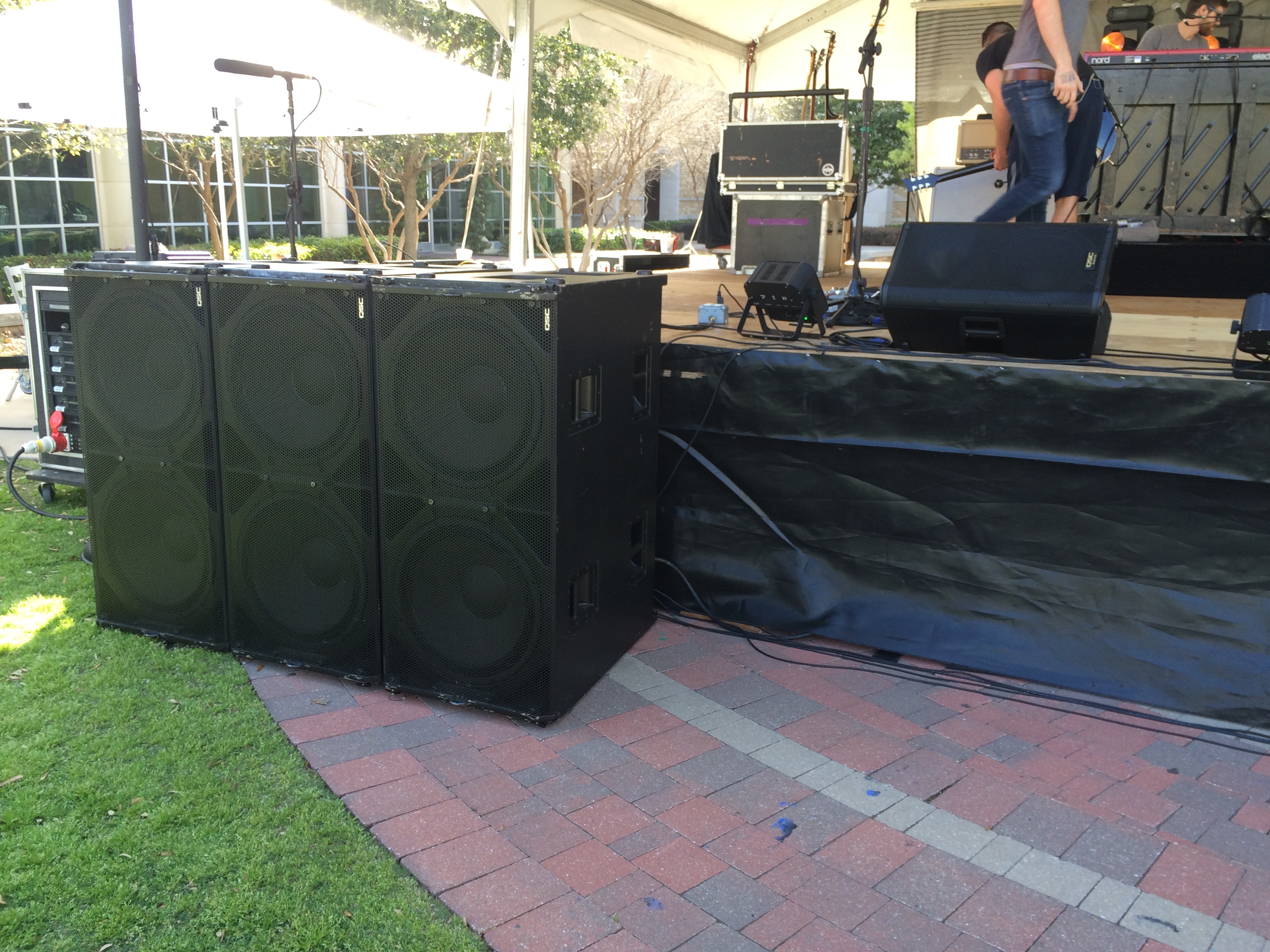
I have been very impressed and pleased with what QSC has offered in the speaker realm. I’ve even seen designers who use Meyer Sound speakers use QSC speakers for less important zones (backstage, rear surround, etc…). Maybe we can find speakers in the QSC product line that will provide a cost effective solution to this venue’s needs.

The QSC speakers that I’m currently researching are the ADS12 (full range speaker) and the ADS112SW (subwoofer).

QSC AD-S12

QSC AD-S112SW

I would consider using one of the QSC self powered models but I am hesitant to use a speaker that has a fan involved. One of the things Meyer Sound does right is use convection cooling. I have installed QSC self powered speakers before when multple fans are running, it’s noticeable. I’m sure the concept is that when the fans are running the speaker volume is going to mask the fan noise but that’s not always the case.

Wind & scrims!

I just finished installing some speakers for an outdoor venue where the system designer was using Smaart 7, a DPA 4007 & a Lectrosonics TM400 wireless kit. As a side note, the engineer is a Meyer SIM3 owner and user. It had never crossed my mind but sometimes the wind is just going to ruin your measurement process and you may just have to wait for a break in the wind. Right off the bat you can expect your low end measurement response to be totally unusable.

One of the other experiences I had on this install was realizing that scrims are NOT acoustically transparent. Anything between a speaker and the audiences ears is going to effect some portion of the frequency response. If you put a speaker right up against a scrim, there is less reflection than when you move back away from the scrim. Interestingly as you move a speaker away from a scrim, as you move away, the frequency of reflection drops. So if you have to deal with a scrim, you’re best off hugging it. The main arrays for the PA were clusters of Meyer JM1P (4 boxes) which creates a curved array. Obviously even if part of it is up against the scrim, part of it will not be up against a scrim. Unfortunately scrims are a necessary part of some sound installations and so we need to know how to optimize any circumstance.

Theme park install – 051115

Tomorrow I start an install job at a popular theme park in San Antonio. The park is about to go to a 7 day schedule until end of Summer so the park is busy getting everything ready.

The new PA consists of:

(2) Meyer JM1P arrays (4 boxes per side)
(4) Meyer HP700 subs (2 boxes per side)
(2) Meyer UPQ center fills
(2) Meyer UPQ side fills
(2) Meyer UM1P ???

All DSP will be performed via a Qsys network.

QSC QSYS – DSP

The JM1P is a 20 x 60 degree box and the shape of the box allows them to be arrayed tightly.

With (4) boxes per L / R array that provides 80 degrees of horizontal coverage x 60 degrees of vertical coverage. Add another box and you get 100×60. Another and you get 120×60 etc… I presume you could make a 360×60 array but I’m not sure what good it would do.

Last week I visited the construction site to look at rigging options. In case it’s not clear by now, aiming your speaker correctly must be achieved before any eq / delay / correction is done. Aim your speakers wrong and you might be wasting your time and money.

Once I’m on site I’ll write more.

Impulse / Phase / Frequency – responses

In order to understand what a transfer function measurement is displaying, you need to understand what the impulse response / phase response / frequency response means.

Abbreviated, IR / PR / FR:


WIKI article – Impulse Response
WIKI article – Phase Response
WIKI article – Frequency Response

In my ignorance, I basically ignored the IR and went straight for the FR (incorrectly thinking of a FFT measurement as a RTA of sorts). Knowing better now, the IR is the very first and most important trace. The IR trace reveals acoustics and secondary reflections that may be caused by poorly aimed speakers, poorly placed measurement mics, etc…

The IR can also provide information about polarity. If the impulse trace shows a peak that goes negative instead of positive, you may have to resolve that issue before doing anything else.

It’s essential to be able to read and understand what an IR trace reveals.

Once you have an acceptable IR (which also provides a time offset between source and response / reference and measurement), then you can move on to the PR and FR traces with confidence that you aren’t wasting your time.

Scott Theater – house PA failure

There must be a better way to tell a house person that their PA has issues than just telling them their PA has issues because doing so wasn’t met with much applause.

During the Dog Days loadin / setup it was discovered that the HR main had an issue. What issue? No lows and no highs but nothing blown???? Strange but very noticeable.

Ultimately we took both the HL and HR speakers down (after labeling them) to attempt to fix the HR speaker and to measure and verify what the issue is. With a working HL speaker that is the same make and model, it will be obvious if there is something wrong.

I have no doubt there is something wrong. I just don’t know what it is yet. Once I measure them both, I’ll post the results and hopefully correct the issue and provide new measurements once they are both fully functional again.

More soon.

Dog Days – Scott Theater

On Thursday we began the load in process for Dog Days (the opera). On Friday the traveling crew arrived. The sound designer discovered that something was wrong with the HR main speaker. No lows and no highs. The box is a Renkus Heinz (????) which has a 15″ woofer and 2″ driver on a horn. I’ll know more once I measure the cabinet against it’s working counterpart but my guess is that a component on the crossover has failed and the phase between the drivers is off now. Both components are working so it’s not a blown speaker / driver. What do you do when you find a malfunctioning house speaker? Take it down and put up a different one of course!

The system consists of the following:

(2) QSC KW122 speakers hung as L / R for mains.
(1) TOA HX5 4 box mini line array for a center cluster graciously left behind by TCU’s Bill Eckenloft.
(2) QSC KW122 speakers hung for side of stage monitors.
(4) Mackie SRM150 hotspot type speakers in the orchestra area.
(2) Mackie SRM350 rear of house speakers for the helicopter

Today we tuned the system.

PHOTOS TO COME

10000 plus visitors

Even if there are only a handful of visitors who are actually interested in audio measurments and the rest are google and microsoft searching for information, audiomeasurement.com has hit a milestone of 10,000 + visitors.

Cheers!

Dallas City Performance Hall – Fulcrum Acoustics

I’m back in a local Dallas venue that has a Fulcrum Acoustic sound system.

The system consists of:

(2) DX1265 for upper main L / R
(2) DX1295 for lower main L / R
(4) US212 subs located in cavities under the stage.
(3) CX5D for under balcony fills
(7) CX5D in the face of the stage for front fills

There is a center cluster that is not a Fulcrum product.

(1) D&B TI10L 5 box line array center cluster

d&b audio – Ti10L webpage

DCPH Stage

DCPH house

This is my 3rd visit to the venue with Texas Ballet Theater. Previously I have known that the system wasn’t optimized but didn’t know enough to know what to do about it. I also didn’t have a relationship with the house crew to start digging into their settings. I have simply measured and Eqed at the board as best I could.

This time, there is enough trust between myself and the house crew to get into the DSP settings and discuss what might be wrong and what might be done to make things better.

What are the issues? The PA appears to have issues of speaker placement and aim. Poor coverage on the sides, uneven response, uneven levels, overlapping coverage, possibly incorrect delay times, speakers that are reflecting off near by surfaces, subs located too close to specific seats, subs mounted in resonant chambers, etc…

If the proof is in the pudding, it simply doesn’t sound very good. The good news is that I think the existing system can be greatly optimized with proper aim & correct processing. Neither of which requires much effort and cost to correct.

Since I haven’t finished gathering the necessary information to go forward with the verification process yet, I’ll hold my final judgement but in the meantime, here are some interesting images…

This is the DSP block that is processing one of the DX1265 cabinets.

Fulcrum Acoustics DX1265 super module blocks

HPF

Fulcrum Acoustics  DX1265 HPF

LPF

Fulcrum Acoustics  DX1265 LPF

LF EQ

Fulcrum Acoustics  DX1265 LF PEQ

HF / LF EQ

Fulcrum Acoustics  DX1265 HF LF PEQ

HF / LF FIR (Finite Impulse Response)
WIKI article – FIR / Finite Impulse Response

Fulcrum Acoustics  DX1265 HF LF FIR

This is interesting,

The upper DX1265 Main L / R boxes have a delay between the HF/LF & LF driver of .438 ms:
Fulcrum Acoustics DX1265 LF delay

The lower DX1295 Main L / R boxes have a delay between the HF/LF & LF driver of 1.479 ms:
Fulcrum Acoustics  DX1295 LF delay

Same box, same dual 12″ LF drivers. The DX 1265 has a 60 x 45 horn. The DX1295 has a 90 x 45 horn. What accounts for the 1 ms+ difference in delay times between lower and upper boxes (between the LF and HF / LF drivers) ???

Dog Days – pre loadin mic check

The Fort Worth Opera festival loadin starts tomorrow. Dog Days is one of the operas in the festival but it’s being produced in a different venue. The Dog Days load in starts on Thursday.

WIKI article – Dog Days opera

NY Times – Dog Days

Here is the input list that came with the show:Dog Days original input list

I have some of these mics and some will be substituted for arguably “better” mics. Some will be substituted with arguably “comparable” mics.

This afternoon I setup a mic test rig using a QSC KW122 self powered speaker. I used the speaker because it is relatively flat and being self powered, took about 1 minute to have pink noise coming out of it. I set up a mic stand at roughly 6′ away from the speaker. The speaker’s HF horn was located at roughly 6′ off the ground with no objects between the mic stand and the speaker.

Dog Days mic test rig

Note that the KW122 has a 3 way switch on the back. The choices are “Ext Sub” (reduces low end), “Normal” (flat response), “Deep” (extends low end). After measuring those 3 settings with the first mic, I selected “Normal” for all subsequent measurements.

This trace shows what the switch does:

INSERT TRACE HERE

Then I proceeded to take some reference measurements using my matched pair of Earthworks TC30K omni mics. Then I measured with my newly acquired Audix TR40 pair (non matched). After that I went through the rest of my measurement mics including an Earthworks M30BX (self powered), TC25K omni and then moved on to the mics to be used in the production.

This includes:

AKG 535
AT 4033
Earthworks SR20 / SR69 (same thing but older model)
Earthworks FM500 (flex mic)
Oktava MC012 / MK012 (same thing but newer model)
Sennheiser E604
Shure SM57
Shure SM58 / SM58S (switchable)
Shure Beta 52A

The Oktava bodies can work with different capsules so I compared all (6) cardioid, (4) omni (2) hyper cardioid capsules.

All in all it took about 3 hours to go through the process of documenting the serial numbers of the mics, measure and save the data.

INSERT TRACES HERE

The Fort Worth Opera festival loadin starts tomorrow. Dog Days is one of the operas in the festival but it’s being produced in a different venue. The Dog Days load in starts on Thursday. Maybe by next week I have some time to update this page and add the measurement data…

How to calibrate your SPL meter in Smaart 7

My AMPROBE SM-CAL1 Sound Meter Calibrator just arrived and I thought I would figure out how to setup an accurate SPL meter in Smaart 7. Fortunately, Rational Acoustic’s “Calvert Dayton” has already provided instruction on how to go through the process via a post on the Rational Acoustics forum. Calverts response is #7.

Re: SPL –measurement does not what it should

Instructions as follows:

1. Open the Amplitude Calibration dialog window by clicking CalibrateSound Level Options button in the dialog (Options > SPL/LEQ…).
2. Select the audio device and input channel that you want to calibrate.
3. Turn on your calibrator and wait a moment for the average to stabilize — say 10-15 seconds for a microphone calibration using an SLC, maybe 20 to be on the safe side. 20 seconds would be enough time to build from -138.5 dB (all 0’s in a 24-bit integer) to 0 dBFS (all 1’s), given a 0 dBFS reference tone.
4. Click the Capture button.
5. Type your nominal reference level (e.g., 94, 104 or 114 dB) in the Calibrated Level field — when performing a microphone calibration in the field you generally want to use the highest output level that your sound level calibrator offers.
6. Hit the Enter key to recalc the Calibration Offset.
7. Click the Apply button.
8. If you want to calibrate additional inputs, go back to step 2 and loop through again. Otherwise click the Done button to exit the dialog.

Here is another website that described the method:

Smaart V7 calibration for SPL

Shure Beta 52a

I have a production coming up where the visiting engineer wants a Shure Beta 52a for the kick drum. I could substitute an arguably “better” mic but I happen to like the sound of a Beta52A on kick drum and it around $125 street price, it doesn’t hurt to have an industry standard mic in my collection. One of the things that manufacturers do to “kick drum” specific mics is to PAD them down so they don’t overload an input. There is usually some extra low end involved.

As a reference, there are many kick drum specific mics on the market and then some non kick drum specific mics that have been used for that purpose such as the EV RE20, Sennheiser MD421 and Beyer M88.

Here are some articles on kick drum mics, none of which provide more than opinion about the difference between the mics they compared:

recordinghacks.com – kick drum mic shootout

gearslutz.com – 11 kick drum mic shoot out

soundonsound.com – bass drum microphones

What does it all mean without measurements to see what is what?

INSERT Beta52A measurement data
INSERT D6 measurement data
INSERT RE20 measurement data
INSERT MD421 measurement data
INSERT AKGD112 measurement data
INSERT E901 measurement data
INSERT Earthworks SR25 data
INSERT Earthworks TC30K data (for reference)

audiomeasurements.com Youtube channel coming soon…

Unfortunately, there is a limited amount of useful information currently on Youtube regarding audio measurements in general. Consequently, I’ve geared up to build a Youtube video channel specifically related to audio measurements.

I’ll be using Camtasia screen recording software to capture the measurement process, add titles as well as edit and assemble non screen video and still media together.

Camtasia webpage

If you have an idea for a video that explains something you want to learn regarding audio measurements, contact me.

[sweetcaptcha_contact_form]

Ineffective acoustic treatment 040715

I just came across some old install photos and thought I would share.

A while back I hung a new sound system at “Pirates Voyage” in Myrtle Beach South Carolina.

piratesvoyage.com

We replaced the existing EAW PA with a Meyer Sound rig designed and provided by Pro Sound out of their Orlando Florida office.

In reviewing the photos of the old rig, I was reminded of what appears to be “acoustic treatment” on the backsides of the EAW arrays.

Pirates Voyage old PA cluster

I can only guess that someone was trying to reduce some of the low end / low mid content coming off the back of the cabinets. The thickness of the padding appears to be about 2 inches. I would argue that 2 inches of padding will cause zero reduction of any sound coming off the back of the cabinets as that sound would be omnidirectional anyway and completely ignore the padding. Whatever resonance was the culprit might of been better served by putting the padding on the inside of the cabinets.

If you want to know how a speaker will behave when it’s producing sound, tap on the sides of the speaker (any speaker / any side) with your knuckles. If it is relatively muted and of higher pitch, that suggests a well braced speaker. If you excite the walls of a speaker when you tap on them and it sounds like a drum, it will sound like that same drum at certain frequencies when it produces sound.

A perfect speaker cabinet wouldn’t vibrate at all. Think of a speaker cabinet being made of concrete. There are some home stereo speakers made of concrete but for professional applications, concrete speakers just don’t make any sense. Speaker design is a balancing act. Cost, weight, performance, etc… IF you brace a speaker cabinet correctly you don’t need to use concrete to get a relatively vibration free cabinet.

If you mount a speaker inside a structure that doesn’t vibrate at all, then all the energy of the speaker will be transferred into the air. Instead we settle for some cabinet vibration but you certainly don’t want cabinet resonances where the cabinet literally sings along. Inexpensive molded speakers typically make for hand good drums. The better the speaker, the better the cabinet design and bracing. Some inexpensive speakers are mounted in a wooden box with no bracing. That might as well be a hand drum. Speaker design is more than porting and cabinetry. A well designed cabinet lets the speaker does all the work.

There is a balance between light weight and good sound.

Flown subwoofers 040615

In the sound reinforcement industry, flown subs is a relatively new trend. In the early days of large scale sound reinforcement even the main PA was typically stacked on the ground, stage or located on scaffolding to raise it up.

What is the benefit of flying subs?

For one when they’re on the ground those closest to them are getting a lot of low end. For instance, those standing right up against the barricade. If you’re 3 feet away from a sub array, it’s going to be really loud in comparison to those who are 30 feet away or 300 feet away. By flying your subs you equalize the distance at which the audience can be in proximity to your subs. Another benefit is that when your subs are flown with your mains you have the opportunity to time align the subs for a larger portion of the audience. When you fly your main speakers and put your subs on the ground, you’ve got a limited amount of time alignment choices and none of them are going to work for the entire audience.

Frequency & Wavelength 040615

I’ve been looking into the concept that a line array needs to be approximately 12 feet long for directional control down to about 100hz.

As you shorten your array, the directional control of your array starts to climb in frequency.

In order to know what frequency your short line array becomes omnidirectional, you can use this website calculator:

MC2 System Design Group – Wavelength calculator webpage

Here are some lengths of frequencies or “wavelengths”.

Wavelength of 100hz

Wavelength of 250hz

Wavelength of 500hz

Wavelength of 1000hz

If the goal is directional control down to to crossover point where the sub kicks in, obvious 100hz / 12feet / 3.44 meters is pretty much a minimum. What if we can get by with a sub crossover point @ 125hz?

Wavelength of 125hz

So we still need 9 feet / 2.75 meters of line array length.

What if we want our directional control to extend below 100hz? How about 50hz? We need 22.6 feet of line array.

Wavelength of 50hz

25hz equals 45 feet! I don’t think I’ve ever seen a 45 foot long line array but I have seen some that are 20+ feet long.

Wavelength of 25hz

What is the benefit of having directional control down to the sub crossover frequency? I’ll have to do some more research to answer this question fully but I can tell you that your stage sound will benefit from not having a bunch of low end and low mid energy coming off the main PA and loading your stage. The concept of putting sound where the people are means the audience and not the stage. The last thing I want is low end from the PA system bleeding into all my stage mics.

Along these same lines are the use of cardioid subs. I would guess that with a long enough array (at least 12 feet) and cardioid subs, you may have very little PA sound on stage which is an obvious benefit to the band / talking head, etc…

Toby Dean Guynn of TOBY Speakers passes away – 033015

Today is a sad day here at audiomeasurements.com…

I just found out that my friend and long time mentor Toby Dean Guynn passed away on March 30th, 2015.

The first time I met Toby, I walked into Toby Speaker Corp on Montgomery with a very simple question. He walked me over to the nearest chalk board and began to explain. I didn’t get the answer I was looking forward. In fact, I think I left with more questions than answers that day. I didn’t realize it at the time but that first Q&A session would lead to a 20+ year friendship with the man. Toby was one of those rare people who understood what he knew very well but was always willing to state “I don’t know…” when he didn’t know something. He was a man who would ride his bike to the bank to make a deposit. A man who never lost his fascination with “good sound” and the pursuit of “better sound”. A musician, artist, recording engineer, inventor and business man who made a career out of selling a good product for a good price with a good warranty. If there is one person who inspired me to strive for being a better sound engineer, gaining better understanding of acoustics, speaker building, recording techniques and just being well rounded, it was Toby.

He will be greatly missed.

Toby Dean Guynn

TOBY Speakers carries onward…

tobyspeakers.com

For those interested, here is a reprint of an article about Toby that appeared in the local newspaper a while back:

A Short History of Toby Corp of America

Amprobe SM-CAL1 – sound meter calibrator


sm-cal1

With a sound meter calibrator, you can verify the output level of a measurement mic so that you know that your SPL measurements are accurate. Yesterday I secured an AMP SM-CAL1 with 1/4″ adapter for around $100 on Ebay. Between the 1/2″ and 1/4″ adapters I should be able to maintain all of my measurement mics.


Screen Shot 2015-04-03 at 8.59.32 AM

AMPROBE SM-CAL1 sound meter calibrator webpage

AMPROBE SM-CAL1 sound meter calibrator data sheet PDF

AMPROBE SM-CAL1 sound meter calibrator product manual PDF

QUOTE:

“The Amprobe SM-CAL1 is a sound meter calibrator with two output levels of 94 dB and 114 dB. The calibrator generates these fixed sound level signals for calibration of sound level meters. The unit ships with a ½” adaptor installed to accommodate sound meters and microphones with ½ diameter.

Battery: 9V, 006P or IEC 6F22 or NEDA 1604.
Electrical (sound) standard: ANSI S1.40-1984 and IEC942 1988 Class2.
Output sound level: 94dB and 114dB re 20 uPa under reference.
Accuracy: ± 0.5 dB.
Output frequency: 1 kHz ± 4 %
Two output levels of 94dB and 114dB
Output frequency of 1000Hz
Fits ½” microphones
Easy one handed operation
Low battery indicator
CE, conforms to ANSI S1.40 – 1984 and IEC942 – 1988 class 2
Includes ½” adapter, 9V battery and users manual

This is taken from the user manual (ENGLISH)


Screen Shot 2015-04-03 at 9.11.53 AM

In a future post I will provide details as to how to use one of these devices.

Wooden Rack Unit spacers 032815

Many times in life you will need to mount a device in a rack without the assistance of a friend.
Sometimes you will need to leave a 1RU space in between devices for thermal reasons.

Sometimes supporting the device while you install the rack screws can be a great challenge. I’ve been known to use my teeth, knees, toe, etc…

I’ve also used audio gear as a spacer before which works if you have a spare 1RU, 2RU, 3RU audio device handy but you run the risk of trapping the device in the rack.

For those of you who may not know what a “rack unit” is, here is a wiki article that explains it.

WIKI article – Rack unit

So 1RU = 1.75″ (inches) tall and 19″ +/- wide

For reference, this is one of my Glyph hard drives measured with a digital caliper. 1 & 23/64 inches. Obviously if a RU is 1.75 inches the gear itself cannot also be 1.75″ or the tolerances for both the rack and the gear would need to be absolutely perfect. So manufacturers undersize their gear just a bit to make sure it fits. Rack manufacturers also build a bit larger than 19″ wide. I’ve had racks that were almost 19.25 inches. In this case the gear I own wouldn’t line up with the rack holes. Most of the racks I’ve measured are 19 1/16″ or 19 1/8″ wide. Plenty to fit a 19″ wide device.

IMG_1299

What might make a good spacer that is inexpensive, readily available and easy to manange? A modern wooden 2″x4″ is roughly 1 & 1/2″ x 3 & 3/8″.

IMG_1300

What this means is that (2) 2″x4″ scraps make great 1RU spacers to support gear while you install the screws. If you make the 2″x4″ scraps long enough and have them stick out a bit, you can use them as a lever to adjust the height of the device you’re mounting.

IMG_1302

I now keep a pair of these wooden spacers in my kit for when I need to shuffle gear around in a rack. They are a bit on the short side so I might put some felt on both sides to make them closer to the 1.75 inches. This will also keep the gear above and below from being scratched by the wood.

To measure or not to measure 032715

Today I had the plan of visiting an outdoor stage and measuring and helping eq and delay a sound system for a fellow audio engineer.

Upon arrival I realized the band was already sound checking and at that point I really couldn’t do much but discuss the elements of the PA and how I would go about measuring it and “correcting” things. Interestingly the visiting FOH engineer had a measurement rig of some sort but the little bit of discussion I had with him and his responses suggest he is using his measurement rig as an RTA and nothing more.

False Alarm 1

A few highlights. It’s not easily seen in the photo above but the front fills were aiming toward the tent roof instead of outward toward where the crowd would later be. When I asked about the front fills, the visiting FOH engineer said that he didn’t need them. How can you argue with that?

I had just left the position I was in standing as close to the stage as possible and at the very middle of the stage discussing with my fellow engineer friend how the Main L/R PA wasn’t covering the center well at all. I guess if you stand down front and you hear anything, it’s all good? There was certainly plenty of subs at that position.

Speaking of subs, there were (6) double 18″ QSC subs split L & R.

QSC subs

The main speakers were hung from Genie towers.

QSC line array

Then there was a pair of QSC KW181 subs with QSC KW152 mains on top of those acting as delays.

QSC delay stack

The delay speakers were at least 80+ feet away from the mains. I was told the visiting FOH engineer had 2.5ms on the delays and I heard him say he had the drummer play to set the delay time. I didn’t say anything but I thought…”Interesting”

In case this isn’t already clear, 1 foot of distance between speakers is going to dictate approximately 1ms of time delay.

If you’ve got 100 feet of distance between speakers you’d be better of setting your delay time between those speakers (delaying the one further out in the crowd) 100ms instead of using your ears and a drummer. It isn’t a terrible method to use a click of some sort to time align delays with main speakers but when you’ve got a measurement app, there is zero reason to guess or not measure or just don’t delay at all. The visiting engineer may not understand how to make the measurement and set the delay time. Absolutely fine. I was in that position a few years ago. To be clear, setting delay times on speakers is one of the easier measurements to make and the easier settings to adjust. You can even verify your work. Once you insert the delay on your delay speakers, measure that zone again. If you’ve nailed the delay time, your mains and delays should measure the same with the mic in the right position and without moving it. Where do you put the mic? Where the two speaker zone (you’re only measuring one speaker at a time right?) cross over acoustically (not in frequency but in volume).

Since the subs were in front of the stage and the Main support lifts were to the side of the stage and back a big, logic would suggest that the subs would arrive early compared with the mains. This could be resolved with either the rack DSP or the FOH console (if subs were on an aux send) but obviously the subs were not aligned with the mains. Instead, the subs were early because when the kick drum hit, I could hear subs and then mains.

Basically, “I came, I listened, I learned, I left…” alll without ever taking my measurement rig out of my backpack.

A few things that became obvious while I was onsite.

1. Owning a measurement rig doesn’t mean you know what to do with one.

2. Front fills are necessary regardless of what the visiting engineer might think. It shouldn’t be left up to them to decide in my opinion. The system should be tuned and dialed in (levels between zones, eq and delay) prior to their arrival.

In this case the visitor engineer brought his own FOH console so it could be argued that being that far along in the system tuning process would of been impossible but I would counter with, “all of that stuff could of been achieved at the DSP in the rack” and should of been. Without a measurement rig and the skills it takes to use it and decipher the results you really are just hiding your head in the sand. I’m not saying it’s easy but I am suggesting it’s necessary.

What I heard coming out of the PA sounded typical of what I expect of bands these days. Too loud, too much low end and lots of compression so nothing has any space. Like it’s all shoved into a bucket. I measured 100+ db on my Iphone at the FOH position and things were obvious louder as I got closer to the stage. I’m not sure things need to be that loud when you’re sound checking a band during the day and no one is around. Maybe I’m too old.

false alarm spl

QSC amp rack and DSP

In conclusion, a digico SD5 with a QSC line array with matching DSP and power amps can certainly sound better than what I heard. It’s clear after this experience that I still have a long way to go in my pursuit of system design and optimization but also in my people skills. If was difficult not to get involved in the whole conversation but no one asked me what I thought. Maybe next time I can arrive earlier and help the situation a bit. If the PA had been time aligned, zones balanced and the system tuned prior to the visiting engineers arrival, I don’t think he would of disliked the system. Instead he did the best he could with what he was given and what he knows. Clearly there is work to be done…

Smaart 7 fails to load and then asks for activation 032615

I just tried to start up Smaart 7 and the software wouldn’t load correctly. Then it said I wasn’t activated and I tried reactivation but that didn’t work either. Then I remember something I had addressed in a previous email between myself and Rational Acoustic’s tech support.

Here is the email exchange:

Imac Smaart activation email

Smaart 7 worked fine yesterday and I know it’s been registered and activated. What has changed on my rig to cause this issue? Based on John’s email explanation, the following came to mind.

Two things.

1. I have an older Imac hooked up to my newer Imac for transferring files.
2. I have an old HD from my MacBook Pro (also registered with Rational Acoustics) plugged into my newer Imac (registered with Rational Acoustics). Obviously those two harddrives are confusing Smaart 7 because as soon as I ejected them, Smaart 7 works again.

Smaart or SpectraFoo Complete?

Now that I own both SpectraFoo Complete and Smaart 7 and have used them both enough to have an opinion, which one would I choose if I could only have one? If it was for measuring sound systems, I would go with Smaart because of the Live IR function, delay tracker and the ability to have multiple overlapping transfer function traces active at the same time. These three things are a game changer in my opinion.

Rational Acoustics – Smaart 7 webpage

This isn’t say that SpectraFoo Complete can’t get the job done. In fact I tend to use SFC for most transfer functions just because I’ve spent more time with the app and know it so well.

Another thing I like about Smaart 7 is that I can capture the FR, PR, Coherence and IR at the same time. For someone like me who wants to share my results, this is ideal. Otherwise I’m left to take lots of screenshots which are hard to manage and impossible to revisit.

Why must one choose between cake and ice cream? I believe that the strengths of both apps used for the right purpose justify the cost of both applications. Metric Halo has lowered the retail price for SpectraFoo & SpectraFoo Complete enough to where I think anyone who works with audio would benefit from having it.

SpectraFoo Complete has instruments designed specifically for studio use (bit scope, bit range meter, phase torch, phase scope, power balance meter, vast level metering options (multitrack audio and Bob Katz K metering), THD analyzer, etc… as well as instruments for live audio purposes. Very useful.

SpectraFoo Complete instruments

Metric Halo – SpectraFoo / SpectraFoo Complete webpage

Line Arrays

One would think that with a market saturated with line array offerings, the old single speaker cabinet would be a dead horse but this is not the case. Just as a hammer isn’t worthless just because a wrench is needed. We need quality tools to reproduce our electrical signals and one shouldn’t make the decision on which tool to use without understanding how to select the best tool for a given purpose.

Here is some reading material to get you started. I’ll revisit this page soon…

WIKI article – Line Array

prosoundtraining.com – Line Array Limitations

Meyer Sound – Line Arrays: Theory, Fact and Myth

ProSoundWeb – Everything You Wanted To Know About Line Arrays (And Then Some)

Soundmansbible.com – Line Arrays vs. Point Source

Sound On Sound – Line Arrays Explained

JBLPro – Analysis of Loudspeaker Line Arrays

Countryman E6 032015

Today I’m guiding assisting a local church in securing some replacement cables and protective caps for their Countryman E6 & E6i mic elements. I previous designed and installed the PA systems in their building.

Most miniature condensor mics have some sort of cap. In this case the protective caps not only keep debris out of the element but also offer different frequency responses depending on which one you use. When looking at the images below note that the flat cap is the shortest and the most extreme HF boost is the longest cap. Considering that the cap slides onto the element housing and we have a glimpse of how very small changes near a mic can have dramatic results. Who would think that the amount of cap housing behind the mic tip would have this effect?

Miniature omni mics (if capped with a flat frequency cap) could easily be used for audio measurements. Some industry standard miniature omni mics include the DPA 4061 (which also has various cap options that affect the frequency response), Sennheiser MKE2 Gold and the Countryman B3 & B6 (both offering caps that affect the frequency response). You wouldn’t want use these mics via a wireless beltpack but if you have a way to get the mic signal wired up, no reason you couldn’t use them for audio measurements. Especially if you can compare them with a known measurement mic.

Countryman E6 protective cap – webpage

E6 user guide PDF

Here is some relevant information taken from the PDF manual.

Countryman E6 manual page 15

Countryman E6 manual page 16

Countryman E6 manual page 13

Countryman E6 manual page 12

Albert Einstein’s office

I got an email from a friend today that included this photo of Albert Einstein’s office when he passed away.
Alberts office

Here is a quote from the man himself that ties in well.

“If a cluttered desk is a sign of a cluttered mind, then what are we to think of an empty desk?”

– Albert Einstein

I think there is a legitimate justification for clutter and chaos. An empty room will sound different than a room full of furniture. Arguably better. Especially if the empty room is acoustically unflattering. I like neat and organized as much as the next person but neat and organized isn’t necessarily superior sonically. With our measurement rigs, this sort of thing is scientifically provable. How? Setup your measurement rig and send some pink noise into the room. Save a trace of the impulse / frequency / phase response. Now clear out the room and remeasure. Compare the results. I would venture to guess that the impulse response will now be much worse (lots of secondary reflections) and the frequency and phase response will have changed noticeably.

Even without a measurement rig, our ears are well equipped to detect ugly reflections. Simple. Clap your hands together in the space and turn around as you clap. Your ears will be provided with a sonic imprint of the acoustic space. The clap is exciting the space in the most important frequency range (the mid range) and you can hear what happens when you load the room with sound. This approach is no substitute for actual measurements but it is a good start. The first thing I do when I arrive in a new venue is clap my hands as I walk around to get an idea of what I’ve come up against. Standing on stage and clapping out into the house is a good test. Standing at FOH and clapping is another good test.

In the case of my office, I tend to let things back up and pile up. I am in the process of organizing right now so before I start the cleansing process I will take some before and after measurements. In the meantime, here are some pictures of what I have done to create some acoustic chaos in the room without just deadening it.

chaos 1

chaos 2

chaos 3

Prior to the added chaos and clutter, my office had an ugly & very short reverb tail. With the added white ceiling and wall treatment, it’s relatively free of reflections now. Things I record in my office are very neutral. In case you’re wondering what all those white things are on the ceiling and walls, it is packing material from a Meyer Sound speaker installation. The squares with round holes in the middle are packing material from some non Meyer speakers. I paid $0 for this acoustic treatment and I would argue that it is superior to a lot of what is available professionally because:

A. It’s completely random
B. It was completely free
C. I kept the materials out of the landfill

Sometimes chaos is a good thing. The desk you see in one of the photos is behind my mix position. There is no doubt that there is little if any reflections off that surface:)

Genelec speakers for measurement mic comparison 031915

I just received the second Audix TR40 measurement mic (discontinued) I have purchased on eBay. I was anxious to compare it with the other Audix TR40 I just received to see if they are close enough in frequency and phase response to use as a ONAX / OFFAX pair. Sometimes I don’t want to put up my matched pair of Earthworks omni’s I use to record and I was curious how well the Audix TR40 would compare to an Earthworks mic.

For my last mic comparison I used a Bose Wave Radio/CD device but this time I wanted something with a little bit more low end reach and also with a known response. I used my Genelec HT205 / 1029A pair in the studio for the sound source.

Here is the specs for the speaker:

Genelec 1029a HT205 spec

Here is the PDF manual for the 1029a which is the pro version with a TRS and XLR connector. The HT205 is the home theater version which has an RCA & XLR connector. Same device otherwise.

Genelec DS1029a

Here is the frequency response data from the manual:

Figure 7 shows the HF response at 0,15,30,45 degrees off axis. Note that the HF change is almost exclusively above 10khz.

Genelec 1029a figure 7

Figure 6 shows the on axis response based on the 4 dip switches on the back. With those dip switches you can reduce the bass response below 1khz and / or reduce the treble response above about 8khz.

Genelec 1029a figure 6

The speaker spec states 70hz to 18khz which doesn’t tell us much. Based on the frequency response chart, they could of easily claimed that it produces 70hz to 20khz. In order to know what is what, we need a +/- spec. For example, based on the frequency response given I would call this speaker 70hz to 20khz +/- 3db. A 6 db window between the highest and lowest frequency level within the provided response. Of special mention is a 3.3khz crossover point between the 5″ woofer and 3/4″ metal dome tweeter. We might expect there to be some phase shift at the cross over point when we measure the speaker. We might also expect to see a phase shift in the low end where the ported speaker cabinet begins to roll off mechanically roll.

Let’s take a look.

INSERT RESULTS.

EAW ANYA sound system 031915

EAW Anya dual column

EAW’s new Anya sound system may be the first entry into a new generation of PA systems. Let’s take a look.

EAW ANYA webpage

Here is an overview taken directly from the website:

EAW Anya is a complete, self-contained, high-power sound reinforcement system that adapts all performance parameters electronically, allowing it to be used in virtually any application. Columns of Anya modules hang straight, without any vertical splay, and Resolution 2 software adapts total system performance to produce asymmetrical output that delivers coherent, full-frequency range response across the entire coverage area as defined by the user. It is extremely powerful and immensely scalable, making it suitable for anything from small venues to the largest stadiums.

Each Anya module includes 14x 1-in exit / 35mm voice coil HF compression drivers loaded on a proprietary HF horn that expands to fill nearly the entire face of the enclosure. 6x 5-in MF cone transducers, arranged in two columns of three, use Radial Phase Plugs™ and Concentric Summation Array™ technology to enter the horn and sum coherently with the HF wavefront. Dual 15-in LF cone transducers use Off-Center Aperture loading to increase the spacing of the apparent acoustical centers, extending effective horizontal pattern control well into the LF range.

The module’s horizontal symmetry ensures coherent summation without anomalies through the crossover regions that result from physically-offset acoustic sources. This provides consistent, HF dispersion and broadband pattern control in the horizontal plane. Each Anya module includes a field-replaceable power and processing unit with 22 channels of digital signal processing and amplification to drive each of the module’s 22 transducers.

Via Resolution 2 software, Adaptive Performance controls all performance parameters of the total array to develop an asymmetrical output profile shaped so that all listening locations as defined by the user receive nearly identical response. By carefully crafting the size and spacing of the transducers, EAW engineers enabled Anya to create radical coverage patterns (i.e., narrowly focused and directed almost straight down) while maintaining an appealing, musical sound quality.

Here are some information related to the ANYA system:

Sound Image To Provide EAW ANYA for Tom Petty Tour
YOUTUBE – Robert Scovill discusses EAW’s Anya system with Tom Petty
Here is an interview with Dave Rat and soundgirls.org where they discuss the Anya system.
Anya system review by Dave Rat

Mic comparison 031515

With FFT sofware / hardware you can measure a microphone’s frequency and phase response easily. How? You need a speaker that can reproduce full range audio (doesn’t have to be flat or necessarily good although that is a good thing in general). Send pink noise through the amp / speaker / self powered speaker / etc…

Place you mic out in front of the speaker. 1 meter is a good distance since that is the distance speaker manufacturers typically use to explain how the speaker was measured by them.

1 meter = 3.28084 feet

Let’s call that 3 feet for this purpose. Probably doesn’t matter but why not try right!

Ideally you don’t want the speaker sitting on the floor (you’ll get extra low end but maybe that’s a good thing for your speaker) and you don’t want your speaker reflecting off nearby objects / walls / ceiling / etc… although even this isn’t a huge deal for this purpose.

Unless you start from an optimized situation acoustically, electronically, mechanically, etc… you’re not going to get an absolute result anyway. Instead you’ll get a response that relates to nothing. What good is this? Now substitute out microphone A with a mic that you know the frequency and phase response for (either one that came with a measurement file or at least a print out). In my case I have a good selection of Earthworks omni mics to use as a reference.

When you compare mics from different brands and models, you may have to make gain adjustments between each mic to maintain the trace upon the 0 db / 0 phase reference lines. Once you have matched basic gain between the first mic and the next, IF your unknown mic measures identical to your known mic, you’re golden. There are some variables to consider. If the mics are not in the exact same position, you will get slightly different measurement results. If the distance between the speaker and the mic changes (even slighting) it would be wise to recalculate the delay offset to make sure your phase trace is correct. If your known mic measures X and your unknown mic measures X, they’re matched and you can assume that the known mic has the same frequency and phase response as the known mic.

Take this a step further and you can test all of your mics periodically (using the same distance, same acoustic setup, same speaker / same settings, etc…) to see if you’re mics are functioning correctly. Unless you have some way to measure a very flat speaker in a very flat acoustic environment, don’t expect a flat response but if each time you test a microphone, it’s measurement result matches the previous one and so on, you at least know that the mic is still functioning. Obviously it would be wise to build a data library for each of your mics as they are purchased so you have a base line of what how that mic was performing when it was new. Mics get dropped, wacked, fall off stands, mic cables get tripped over. If you can test your mic selection and verify them against a measurement you made when they were new, that is great. How many old SM58s would test the same way decades later? How would an SM58 made this year test against one that was made 10 years ago? 20 years ago? 30 years ago? etc…

Ignoring the effect of age, moisture, internal windscreen deterioration, etc… I bet the sound of an SM58 has changed over it’s 50+ years of production. Do you know?

I only own a few SM58s. Nothing really old and nothing really new. Next time I have my rig set up I’ll test the ones I have and see how close they are to each other.

Here is another use for FFT software / hardware. You can compare mics that should measure the same to see if they do. Unless you are using mics that come with a custom frequency response print out like high end mics do (per serial number), the frequency and polar response shown in the literature is either a sample from one batch, an average of multiple mics or even worse, a mic that was hand picked because it measured the best. No way to truly know even if you ask. The trace we see in the Shure literature for the SM58 may be from the 60s. Do they update that frequency response and polar response each time they shift the manufacturing process? Do they measure sample mics from each batch? Do you know?

Quadcopters for audio purposes ???

I recently purchased an $80 SYMA X5C1 after seeing some of my fellow crewmembers playing with some quadcopters during the 2014 nutcracker run. I’ve always been fascinated with RC airplanes and helicopters but the quadcopter put me over the edge. I’m officially hooked! Way better than a video game. 3 dimensional flight.

What do quadcopters have to with audio? On the surface nothing really.

They’re a blast to fly around a theater before doors and after the show is over. A sort of toy to release the stresses of doing theater sound design. That is probably enough right there since I rarely “relax” in my role as resident sound designer for various arts organizations. Adding a quadcopter drawer to my workbox will be a good thing.

With regards to audio purposes, I can see how in the future I will be able to use the HD video camera function on a quadcopter to collect information about flow speakers and other things that are out of reach, etc…

I fly a small PA made up of QSC KW122 speakers for some of my ballet gigs and sometimes I’m not sure how the rear settings ended up if I’m not there to fly the speakers myself. Last time I brought them back down to check. Next time I’ll fly my drone up to take a look.

More expensive drones can broadcast real time video to the RC remote. In the future we will see drones mounted with 3D laser scanners that can map an entire venue and render out a CAD drawing. This will be handy for doing acoustic models of a space with prediction software like Meyer’s MAPP.

There are already drones that can fly preprogrammed paths. These sorts of aircraft make shooting scenes for movies and videos possible where a helicopter would not work.

There is a new quadcopter option coming out that not only follows the action but can link multiple quadcopters to the same target and follow them without any piloting. This is called “swarm”.

Plexidrone website

I’m sure the entertainment world will benefit greatly from having inexpensive drones. How about a drone with a wireless measurement mic mounted to it? Near field measurements of the drivers in a line array anyone? Who knows. Once you can program something to fly around in a certain way at a certain speed and follow a predefined path, there are all sorts of possibilities. Lead singer for a rock band being filmed from 4 different angles and broadcast live via the swarm function as they fly over the audience? It will happen…

Bose Wave Radio / CD 031515


I recently inherited a Bose Wave Radio / CD player.

Bose Wave Radio CD top

Since the device has an AUX IN, I can measure L & R speakers separately and their combined response. I’ve always heard good things about the Bose Wave System from people who own them. This will be an interesting experiment for several reasons. First of all, this will be by far the smallest stereo “PA” I’ve measured to date. Secondly, if the device sounds great and measures great, it will mean that I can use it as a reference for my studio mixes. If it measures well but sounds terrible or if it measures poorly but sounds great, that will be interesting to try to understand. Does the Wave System produce good sounding bass that is time aligned with the rest of the audio? Since the audio comes out the front but the bass is mecahnically ported out the back, maybe they are severely out of time.

Bose Wave Radio CD connections

WIKI – Bose Wave System

Bose Wave System related Google Patent page

Bose Wave Radio / CD official webpage

Owner’s Guide PDF

Quick Setup Guide PDF

Sadly the official owners guide provides almost zero information about the device itself. What is the frequency response? Phase response? What size are the drivers? Sensitivity?

Combing the 31 page user manual, the following screen shot is the only piece of information I found regarding the design of the device regarding it’s sound generating mechanics.

Bose Wave Radio CD design

Here is a cad drawing of the bass chamber:

Bose Wave Radio cad drawing top view

Here is a image from the Bose website showing how the rear of the two drivers creates ported low end that mixes together and comes out the rear of the device:

Bose Wave Radio CD bass chamber diagram

Stay tuned for the measurement results…

Sound System Design and Optimization with Bob McCarthy podcast


Today I stumbled onto a podcast with Bob McCarthy and Nathan Lively. Do yourself a huge favor and listen to it. Then think about what Bob has to say and listen to it again.
You can listen to the podcast here:

Sound System Design and Optimization with Bob McCarthy and Nathan Lively

This podcast primes the listener for understanding why Bob’s book is a MUST READ and worth whatever energy it takes to master the topics he provides. If you don’t already have it, go here and buy Bob’s book:

Sound Systems: Design and Optimization by Bob McCarthy

Location, Location, Location 031515

Whether you are designing a PA for a permanent installation or using the same PA day after day for temporary sound purposes, there is probably nothing more important than how and where you place your speakers. This includes the physical location of the speaker / speakers and how they are splayed and aimed.

In the real estate industry, the (3) most important factors to consider when purchasing a piece of property (with or without a building on it ) are LOCATION, LOCATION, LOCATION.

The same thing is true for speaker placement. One of the main reasons I put this website together was because I continually see audio engineers fail to follow the basic principles of speaker placement and speaker combining. There is a right way and a wrong way to do this and if you’re going to spend the money on the gear, you owe it to your audience and your clients to learn how to locate and manage your speakers. All of them.

When it comes to speaker placement, splaying and combining, Success is NOT an accident. There is no point in beginning the measurement and tuning process IF your speakers aren’t properly located and combined.

How do you know?

The shortest path to knowing is to read documents created by the fore fathers of this industry. Specifically, Bob McCarthy’s “Sound Systems – Design and Optimization”.

A spoiler alert. There is nothing simple about this matter. I’ve been studying sound system design and optimization for over 5 years and I still have a long way to go. Why do it at all? Because we don’t have a choice. If you use speakers, you are shorting your earning potential and your clients if you don’t know at least the basics about how speakers interact with a room and each other.

TDO stage monitors 031115

In previous posts I’ve explained that stage monitors should get the same attention given to the house PA. This post will provide further prove as to why.

It may seem unnecessary to tune stage monitors but they are speakers and obey the same laws of physics that speakers aimed at the audience must obey. Any full range speaker is a compromise between frequency response, phase response, bass extension, coverage pattern, cost, size, etc…

If there were such a thing as a “perfect speaker”, where would it measure perfectly? Pick an acoustic situation to optimize any speaker for and then change the acoustic situation. The frequency and phase response will also change to some degree (large or small). This is absolutely guaranteed. There are literally unlimited elements that can and will modify the frequency and phase response of a speaker or speaker combination. For example, boundaries such as the floor, ceiling, walls, corners where those boundaries meet, reflective surfaces, other speakers, etc…

Consequently, no matter where you place your speakers, you will need to make sure they are aimed correctly, splayed correctly and processed correctly, (using delay and complimentary (corrective) equalization if you want a relatively flat frequency response (which you do).

For the production this post is based upon, I came in to measure stage monitors prior to the final dress rehearsal for an opera production. This is actually the first time I’ve every measured stage monitors only. Traditional opera uses no amplification for the audience but does provide pit foldback (stage monitors) so the singers can hear the orchestra regardless of where they are on stage. The singers might be placed behind scenery and need to sing in time. They may be up on a set piece and too far away from the pit to hear the orchestra directly. On the roving carts is a TV as well that shows the conductor camera. Obviously whatever is being reproduced on stage is going to affect what the audience members nearest the stage hear if it’s not properly managed. Proper management of stage monitors includes how they are aimed and equalized.

With that all stated, let’s tune some stage monitors shall we. In this case the stage monitors are Renkus Heinz self powered cabinets. (model numbers to follow)

There are (4) roaming AV carts on stage that include a TV and a speaker with a 15″ woofer / horn. (3) of these roving carts are SR and (1) is SL.

tdo rover

There are also (4) smaller speakers flown overhead as split pairs. One pair is upstage, the other pair is downstage.

tdo overhead

(6) zones total. Each with it’s own level and eq control at the house Yamaha PM5D console (located backstage).

I set up my measurement rig and fed pink noise out of my Metric Halo 2882 into a spare channel on the PM5D console. I also fed another 2882 output right back into an input (creating a loop) to use as my reference signal. I plugged my Earthworks TC30K into input 1 of the Metric Halo 2882 and verified that P48 (phantom power) was turned on. Now I have a way of generating pink noise and sending it to all the speakers as well as a way to measure what comes out of the speakers and what comes out of my audio interface. I have a mic on a stand and with a long XLR cable to move it to the various positions on the stage. The physical loop out of my audio interface which is going right back in to my audio interface allows me to compare what is leaving my measurement rig with what is coming back from the microphone.

Using the Transfer Function instrument in SpectraFoo Complete, I configured my reference to be the loop and my source to be the measurement mic.

Here is a screen shot of the pre and post EQ for the rovers. Notice that in every case, there is excessive low end prior to tuning the zone (post EQ).


Rover#1.
Rover #1

Rover #2
Rover #2

Rover #3
Rover #3

Notice the frequency and phase traces for Rover #3. Pretty ugly. Signs of comb filtering. Certainly the worst of the 3 rovers. Rover 3 is near a black hard leg. This is the main difference between Rover 1, 2 and then 3. Rover 1 and 2 are in a relatively open area.

Regarding the last rover, we didn’t measure Rover #4 because it was a mirror of another Rover we did measure. We were also running out of time. We made a copy of the mirror rover’s eq setting and pasted it on that mix. It would of been better to verify things but you have to pick your battles.

Regarding the overhead speakers, a quick measurement of the upstage pair suggested that there was no need for EQ (given the time we had left). The downstage pair needed a slight EQ adjustment but I forgot to save a snapshot of that pre / post measurement before we stopped. Nex time. What I do have regarding the overhead speakers is a text book example of a horrible impulse response.

TDO WOH OH pair

Notice the indicated multiple arrivals. We would expect there to be (2) peaks if the mic wasn’t exactly centered between the two speakers being measured but the “mess” that is shown indicates that the speakers themselves are reflecting all over hard surfaces which is smearing the sound. Considering the set that was in place at the time which is essentially a bunch of hard walls wrapped around a raked stage in the middle, this is certain. If time allowed, we would ideally re aim those speakers to avoid reflections and improve the impulse response which is really a window into the quality of sound that you are measuring and presenting to the singers but this time, we settled for quick and dirty.

Speaker photos courtesy of Gregg Pearlman

pilot error rig malfunction 030315

If you ever feel really good about your measurement rig and your skills, volunteer to show someone how it works and how to test a piece of gear. For some strange reason, for me this always reveals how far I still have to go. When I work by myself I typically have good results.

So this is what happened most recently. I was doing a show and the house audio personnel asked me a question about their rig. I explained how I would go about trouble shooting what they described and said I was glad to help them. They brought me their Mackie mixer & their audio snake. I setup my SpectraFoo rig and configured it to test the mixer. When thought I was ready I sent pink noise to the mixer and back out of the main mono output. I got a very strange reading.

pilot error rig malfunction 4

To verify that my rig was working correctly I bypassed their mixer and looped out of my rig and back in again. Same behavior, different gain difference.

pilot error rig malfunction 5

Notice the delay finder impulse response:

pilor error rig malfunction delay finder 1

Like a skipping stone. I’ve seen this sort of behavior before (outside of the FFT instrument) when a signal is clipping. I also noticed some weird behaviors in the Mio Console itself. Trying to adjust the gain for the return channel was very touchy.

To make a long story short, it turned out that I was creating a feedback loop by NOT muting the return channel in the Mio Console.

Here is what I had. Notice that my return channel is feeding the MAIN buss. Perfect feedback loop.

pilot error rig malfunction mio 1 annotated

Once I muted the return channel like this:

pilot error rig malfunction mio 2 annotated

Everything was stable and this is the measurement I was able to get measuring the internal signal generator against the D/A A/D physical loop:

pilot error rig malfunction 8

This was a 15 minute detour and once again reminds me that the key to measuring is to build a rig, label everything and how you use it, build whatever configuration files you need in advance and test. Otherwise one routing mistake and your rig doesn’t work.

It turns out that the Mackie input to output was all good. We discovered some broken solder joints inside the snake box due to a failed strain relief. I tried to resolder things but the snake proved to be of such poor quality that the fix didn’t work.

Coherent – what is it and what does it tell us

There are a few instruments / windows & traces in a modern FFT tool.

These would include:

IR (impulse response). Typically in it’s own window. One of the first things you need to do when measuring a digital or acoustic signal is perform delay compensation so the two signals you are comparing are time aligned. If not, youre information will likely be faulty.

PHASE. The phase response is typically in it’s own window. It shows you the time different at each frequency between the two signals you are comparing.

AMPLITUDE (SIM3) / MAGNITUDE (SMAART) / POWER (SpectraFoo Complete) – These are all the same and relate to level.

If two signals are identical in time, phase & level, you get flat lines on your instruments.

Mansfield ISD PAC 030115

Another year has come and gone as I do another Texas Ballet Theater “Peter and the Wolf” performance at Mansfield ISD’s PAC.

Same JBL Vertec PA. The house audio engineers Bret & Daniel were a pleasure to work with again.

For a refresher, here is the first post I wrote about the venue.

Mansfield ISD PAC 021214

One of the things I have learned about measuring Line Array’s is that there is nothing magical about them. The overlap between each speaker in an array is ugly just like an array of speakers turned in the horizontal direction (like everything was done prior the rediscovery of line arrays in the 1990s).

So you have to choose where you place your measurement mic on a line array. If you walk forward and backward it’s fairly easy to hear where the HF (high frequencies) affect each other. I chose to put my mic on axis of one of the line array cabinets. The general rule is to make EQ decisions where it does the most good for the most people. I’m assuming that there are more people on axis of each line array speaker than in between them…

If you place your mic off axis of two speakers in an array you get a very different measurement than you do if you place the mic on axis of only one speaker. Next time I show this but I didn’t think to capture a trace with the mic in different positions (on / off) axis.

RF scanners and RF coordination software

Part of being a live audio engineer includes understanding and using RF (wireless) gear. In order to coordinate frequencies (make sure devices are tuned to compatible frequencies) and avoid interference from other sources like DTV and nearby RF gear, it’s vital to be able to see what the frequency spectrum is and find open frequencies. Otherwise you’re playing Russian roulette. There are many options when it comes to RF scanning. Some are handheld. Some are based around a computer.

This device is a stand alone unit that can be combined with a computer.

RF Explorer’s RACKPRO – rack mount RF scanner

Here is an alternative link to the same information:

RackPro

RackPro – demonstration video

Here is the PC software that comes with the RackPro unit.

Clear Waves – white space finder

Here is the Mac software that can be combined with RackPro.

RF Venue

Here is IAS (Intermodulation Analysis System) software by Professional Wireless

Professional Wireless IAS

Here are some handheld scanner options:

Various RF scanner hardware / analysis software links

Dave Lawler visit to WOH 022415


On a large and complicated system, it’s very important to collect as much information about all the various speakers / processing nodes / etc… as possible prior to starting the optimization process. Coming into a system that isn’t right means that you’re gonna run into all sorts of things that are either incorrect or need to be figured out and then addressed.

Here are some things we didn’t know prior to starting the process that should be discovered in advance.

All makes and models of speakers in system.
Complete understanding of how DSP is configured (inputs to outputs)
Manuals for all the devices in the chain so you can reference them for answers when needed
Verify that all the various speakers are working (zone by zone) & if not, know what is wrong
Understand how the signal chain works so you know how every passive speaker is fed from which amp
Understand your signal chain between console, DSP and any self powered speakers

If you have someone come in to tune & optimize your system and you don’t have this knowledge, instead of optimizing your system you’re going to need to gather the information anyway. In some cases, you may not get to the actual work you wanted to do. I would suggest that you spend a few days prior to any tuning / optimization visit by someone gathering every shred of information you can about your system.

So let’s assume that you have done all your homework before the time is set to measure / tune / optimize your PA.

Here is a drawing that Dave Lawler made for the local crew to setup his mics the way he wanted them.
WOH mic plot

(8) mics are shown. We never got to using all (8) mics because we ran out of time and so many other things needed addressing. Instead we used the (6) Josephson C-555 mics Dave brought with him and moved them around. It’s really important to label the mics and the snakes and cables you use for each mic so that when you need to reference different mic positions you can know with certainty that you’re measuring with the correct mic.

Josephson C550 measurement mics

Dave is a Meyer SIM3 user and brought his SIM3 rig. When we opened up the case, the power button was stuck and the rack ear was bent. Obviously the case took a hit at some point between giving it to TSA and getting it back. We had to pry the power button out to get the device to power on and stay on.
SIM3 damaged during shipping

So what did we do?

The biggest task was to tackle the house L/R line arrays which weren’t hitting the front rows or the upper balcony. I contacted Renkus Heinz so we could verify the settings in the RHAON software (allows for DSP at each speaker box). In that process we were given the following factory settings for Renkus Heinz VLX3 box.

RH VLX3 engineering settings

Along the way of verifying that the settings per box were all set up correctly on the main RH line arrays, Dave discovered that some of the boxes were delayed incorrectly and others weren’t. This isn’t a good thing. Getting a single VLX3 box setup correctly was a task in and of itself but then getting all 24 boxes setup correctly was another task.

Once we had appropriate house staff in place, the main line arrays were dropped and the angles were adjusted to attempt to reach the upper balc without losing any coverage down front. This required changing the support point which mean that the entire array had to be disconnected from the support structure. Since a 12 box array weighs more than 2000 pounds, we removed all but 4 cabinets. Once we had the angles set as per Dave’s model, we began to add cabinets back until we had a complete array again.

The end result is and array that curves up at the top and down at the bottom where as before the array was more like a J which left the upper balcony poorly covered.
WOH rehung line array

Once the main arrays were rehung and tuned, Dave tackled the front fill speakers and the upper balcony fills which cover the last (4) rows of seats.

WOH upper balc speakers

Dave Lawler visit to WOH 022315

Tomorrow I’m scheduled to assist Meyer SIM 3 operator and sound system design and optimization engineer Dave Lawler with some optimization plans for the Winspear Opera House. Dave designed and installed the current Meyer sound system @ Bass Hall in Fort Worth. He was also the FOH engineer for Diane Krall for over a decade. I wasn’t available to participate very much with the Bass Hall measurement process so I’m looking forward to this project.

I’ll post through out the process and hopefully be able to share some useful information once the project is complete. The plan is to reaim the main Renkus Heinz line arrays, re delay and eq all the system parts and solve any issues where possible without adding speakers. This process will reveal any need for future adjustments.

More soon…

Measurement mic positioning failure

On my last measurement session, after setting some delay times, I visited the mic location and realized that the boom had fallen down and the mic was near the floor and not aimed at any speakers anymore.

mic fail

Obviously the results you get down between a seats and not on axis of the speakers being measured is a bad thing. You may be able to tell in the picture that the rubber washer at the boom arm base is bulging. From now on, I’ll make sure the boom is tight. If it can’t be made tight, I’ll change out stands. Obviously your measurement mic might suffer damage if the mic bangs into something.

As a side note, any windscreen affects the response of a mic @ high frequencies. Unless there is a reason to use one (like you’re outdoors), don’t. In this case, my assistant put it on and I didn’t know it.

The impulse response window and easy mistakes to make when setting delay times

If you get a impulse response that doesn’t seem “clean” verify that you’re only measuring (1) speaker. In this case, I was told that we only had one speaker active but it turned out that there were (3) producing pink noise. The one I wanted to measure and then two up on another level. This is the sort of impulse response you would expect from measuring (1) speaker.

Screen Shot 2015-02-14 at 8.47.33 AM

This is what I was getting when there were (3) producing the same pink noise.

Screen Shot 2015-02-14 at 8.47.20 AM

When you’re measuring something, always make sure you’re measuring what you want to be measuring or your results are of no value. Your IR (impulse response) window is your first line of defense against false measurements since in order to have useful phase information displayed you have to calculate your delay at the beginning of the measurement process. If you change your mic placement, your delay time changes and will need to be recalculated. If you’re using Smaart 7’s LIVE IR tool, your impulse response information is updated in real time as you move the mic.

Merry Widow ballet 021715

I’m about to finish a production run of an old classic ballet called “Merry Widow” which premiered in 1975. It’s a fun show and beautiful to watch. Enough about the ballet though.

A few audio facts right off the bat here.

The only playback involved (besides rehearsal music) are some glass breaking cues when the dancers toss their champagne glass offstage that I recorded in a warehouse. The production benefits from having an orchestra in the pit. The house PA system is severe overkill for a production like this but there is still a need for a well thought out small PA to cover announcement duties, provide broken glass sound to the majority of the house and to provide a touch of orchestra enhancement for seats not near the pit.

In order to make sure those near the front of the theater (nearest the stage) have a quality experience, I located a “practical” speaker offstage near where the champagne glasses are supposed to be crashing. For those who are further out in the venue, the “practical” won’t translate correctly so I’ve also added a bit of the same glass breaking sound to the house left speakers being careful to avoid having too much in the house. House audio engineer Doug Kirk, IA sound engineer Paul Strong & myself spent a good deal of time balancing out the glass sounds between the practical and the house left PA to make sure everyone could still believe the glasses were actually breaking offstage.

Speaking of the house PA, I have been flying (4) QSC KW122 speakers. (2) per side as lower and upper pairs. The upper pair is meant to provide coverage to the upper balconies. The lower pair covers from the pit edge and up to about the 4th level balcony. Realistically there is probably too much overlap but if I splay things out vertically any more, I will either wash the pit or wash the ceiling. The first time I tried this PA concept I flew (3) pairs as lower, middle, high but it was obvious that the middle pair wasn’t needed and only made things worse.

This time around I considered whether only (1) pair can cover the entire venue but decided that while it may work, it doesn’t allow for any error or flexibility. For instance, if the upper balc needs more volume, there is no way to provide it. Logically if the far balcony is twice as far away from the pit as the orchestra seating, in order to maintain a consistent level, the upper pair of speakers needs to be louder.

Consider this.

The seats closest to the pit are getting direct orchestra sound. As you move back in the house on the orchestra level, you lose direct view of the orchestra and so you lose direct sound. Consequently as you move away from the pit, the high frequencies are blocked by the pit wall and so we need to add some sizzle back to the orchestra. This is accomplished by micing the orchestra which is primarily done to provide fold back (stage monitors) for the dancers. Those same mics are used to enhance what is missing. Not to make things louder but to make things intelligible. As you move upward in the venue, you begin to see the entire orchestra again at which time you don’t need the same enhancement as you do on the orchestra level. Now the issue is the matter of balance between the brass and percussion sections and the wood and string sections. When the brass and percussion are playing loudly there is no chance the woodwind and string players can compete and they are buried. The upper speaker pair needs to avoid adding any brass or percussion but enhance the strings and woodwinds a bit.

(3) zones with (3) distinct needs.

Zone 1 is covered by the live orchestra but still requires coverage for announcements and sound effects.
Zone 2 relies on the lower speaker pair to add the top back onto the orchestra (due to the physical obstruction). Zone 3 relies on the upper speaker pair to balance out the strings and woods with the direct sound of the brass and percussion section.

So we’re stuck using (2) pairs of speakers doing different things but overlapping a bit somewhere between the 2nd level box seats and the 4th level balc.

Trueman “Monty” Montfort – FOH engineer for Kenny G

I was recently asked to advance the production details for an upcoming Fort Worth Symphony Orchestra pops concert series with Kenny G.

The FOH engineer’s name seemed familiar when I saw it. Trueman “Monty” Montfort has been mixing Kenny for over 20 years and it turns out that Monty and I spent Sept 01, 2001 together during a Michael Bolton show with the Fort Worth Symphony Orchestra.

Monty had mentioned needing time to “tune” the PA and I was looking forward to watching a veteran sound engineer work his magic. When the time came instead of a laptop running FFT software and a measurement mic he used his voice and a house Shure SM58.

I admit I was a bit disappointed. I had this idea that I would get some Smaart training and learn a few things. (SPOILER ALERT, I did…)

So I went about my other duties and upon my next trip to FOH, I left my phone recording audio as I headed back to the stage. What Monty was doing with his voice and an SM58 was interesting. I could tell that in spite of not using a “measurement rig” he was on to something. He methodically went through the system zone by zone adjusting output EQ on the rented Yamaha PM5DRH (his console of choice). I was busy assigning DCA’s on the house Soundcraft Vi6 (covering all the orchestra mics) with my back to Monty. He began to work on the subs and without looking I would swear he was triggering a kick drum sample.

I turned around to see him banged his FOH TB SM58 windscreen down on the padded console rest.

Monty spent 30+ minutes “tuning” the PA and tune the PA he did. A few notes before I forget them.

HELPINSTILL PIANO PICKUP

The Helpinstill piano pickup system Monty brought is a great device. In case you don’t already know about it, it works like a huge guitar pickup that picks up the piano string motion so there is no chance for feedback and there is no bleed. The resulting sound is not quite “classical” in nature and given the choice I don’t think anyone would prefer a Helpinstill over a good set of mics with an open lid piano but if the lid is going to be closed, the Helpinstill has my vote. The sound is clear as a bell and free of the typical muddiness that comes with a closed lid piano with mics in side.

Next,

STRING MICS

NOTE TO SELF: “Overhead mics for string (violin / viola/ cello / upright bass) amplification when in a shell with a band and stage monitors are worthless”. Based on what was available for rent locally, we used 24 Countryman Isomax 2 cardioid mics on strings.

(6) violin 1
(6) violin 2
(6) viola
(4) cello
(2) bass

Since there were more string players (10,8,7,6,4) than we had mics I put up some Earthworks P30 cardioids. I figured this would be a perfect time to compare the difference between close mics and overhead mics without any risk since Monty had no interest in using the overheads. So they stayed muted but I listened to them in headphones from time to time. Absolutely worthless in this situation.

If DPA 4099V,C,B had been available for rent we would of used those but they weren’t.

Unless someone knows something that we don’t the mount option suggested by Countryman for mounting an Isomax 2 on strings is not a very good solution. We rented of the DPA 4061 (omni) rubber bridges and those proved to be a poor solution too. The cable thickness on the Isomax 2 is just too big to fit the notch on the rubber bridge and consequently the mic has a tendency to fall out or rotate around. More than once I had mics that were aimed away from the instrument. We had to reset the mics in the rubber bridges at intermission and before the shows. Prone to failure…

This is where the DPA 4099V (violin), 4099C (cello), 4099B (upright bass) shine. The same mic but custom made mounting options for each instrument.

DPA 4099 microphones

Good stuff. Certainly the best string mic options I know of if you’re going to be in a less than ideal environment. Monty and I agreed that next time, we’ll plan for them.

Moving on or backwards, how on earth do you tune a PA with your mouth and an SM58. No one would agree that an SM58 is a measurement mic and yet Monty used it to tune the PA so I find myself in a conundrum. I’ve got literally thousands invested in software (Specra Foo Complete & Smaart), hardware (mics, a laptop, audio interfaces) and years trying to master the art of FFT measurements and along comes an old road dog who just “wings it”.

Saint Andrew 012015

I was recently contacted by the musical director for a local church requesting that I take a look at the current PA system and suggest how to optimize or make upgrades.

I requested some photos and these are what I was provided with. The labeling was added by the musical director. Very helpful!

St Andrew 3

St Andrew 1

St Andrew 2

St Andrew 4

You may have noticed that they currently have one (1) main speaker! Obviously at some point there was another speaker but some how it was removed and not reinstalled and no one I met knows why.

St Andrew pano FOH

Here is a top view floor plan of the room:

St Andrew top view

The system consists of the single main speaker on the house right, the ceiling speakers and (2) JBL speakers in the rear of house behind the pipe organ facade (one of which is disconnected).

I explained what happens when you have (1) speaker on (1) side of the room. Assuming the one speaker can cover the whole space (doubtful), obviously those sitting furthest away from the one speaker are getting less volume than those sitting closer. Then add to that lop sided system the (10) overhead speakers (all being fed from the same signal) which obviously means they are not delayed. Even worse since they all point straight down at the floor, they excite the floor. The room is not a bad sounding room acoustically but I would guess that when the system is used AS IS, it leaves a lot to be desired. The building was constructed in the 70s. What are the chances that those ceiling speakers are still operating at 100%? Most of the speakers I’ve seen that are that old need some maintenance. Especially if they were ever powered without some sort of high pass (HP) filter to protect them from low end. One of the reasons the church uses both the ceiling speakers and the one main speaker is because the one main speaker can produce some low end.

In case you don’t understand this already, small speakers don’t like low end. Small speakers (in general) have a a small travel range.

When looking at speaker specifications, there is a parameter called “Xmech” which indicates the maximum cone excursion before damage results.

Here is a WIKI article on speaker specs

WIKI article – – Thiele Small speaker parameters

Consequently, very small speakers or speakers designed for only voice or low SPL applications should be high pass filtered or else you risk damaging the speaker / speakers.

On my next trip to St Andrew, I will test the speakers in the system as well as possible. One of the issues with 70v speakers is that there is no easy way to test them separately other than to listen to them as close as possible. In the case of the ceiling speakers in this venue, I will need a tall self standing ladder or a powered lift to reach each speaker. Unless they have been replaced in the recent past, I would bet that they have been allowed to attempt to reproduce excessive low end which would also suggest they have pushed into over excursion at some point.