GK RB800 Bass amp & Hartke 4x10XL cabinet

The combination of a GK RB800 bass amp and Hartke 4×10 XL bass cabinet is one of the most popular combinations of all time. You can rent this rig in any major market. What makes this rig so popular?

INSERT PHOTO OF RIG
INSERT PHOTO OF RIG WITH MIC AND DI
INSERT GRAPH OF DI / MIC CLOSE
INSERT GRAPH OF DI / MIC DISTANT

Meyer Sound Design Reference page 168 – Stage Monitors

This is one of the most important illustrations I’ve come across explaining comb filtering.

Meyer Sound Design Reference page 168 - State Monitors

The Meyer Sound Design Reference is definitely worth owning if you’re still practicing the basics. I have it and Bob McCarthy’s newer book, Sound Systems – Design and Optimization in my library. Together they paint a pretty clear picture. I like the black and white nature of MSDR and the color nature of SSDO.

Here is a link to the actual MSDR book.

Meyer Sound – Meyer Sound Design Reference book
MSDR – Table of Contents
MSDR – The Goals and Challenges of Sound Reinforcement
(c) Meyer Sound 1998

Meyer Sound – Buford Jones | Mixing Workshop

I just finished a two day mixing workshop with Buford Jones sponsored by Meyer Sound.

Screen Shot 2014-08-23 at 11.31.36 AM

Meyer Sound – education calendar

The event was hosted at Sound Productions in Irving Texas.

Sound Productions – website

Buford 3

For those of you who might not recognize the name or the face:

Buford Jones Profile

Meyer Sound brought the following gear for the workshop:
(1) Digico SD8 console
(2) Meyer Sound UPJ (junior) for main L/R
(3) Meyer Sound – UPM-1P for rear L/R and front fill
(4) Meyer Sound M1D Subs in a mono cardioid configuration
(1) Meyer Sound Galileo 616 – PA processor
(1) Meyer Sound Sim3 – audio measurement tool
Meyer Rack

Meyer 500HP

Highlights of the workshop include hearing Buford share his board tapes (reproduced on a Meyer PA adjusted for flat frequency response), hearing his stories behind mixing some of the biggest artists of all time and witnessing him in action as he uses multitrack sessions and multimedia to help explain concepts and demonstrate how he approaches a mix from scratch. Buford has a unique perspective in the industry. This workshop is highly recommended!

Once I have time to go through my notes, I’ll provide some information I think is worth repeating…

Buford 4

Here is a video sample of a different Mixing Workshop with Buford.

Pro Audio Systems & Meyer Sound Seminar Series – Buford Jones 2013

Buying a used Metric Halo 2882 2D / 2D +DSP / Legacy / Legacy +DSP on EBAY

I’ve purchased (4) Metric Halo devices brand new. I’ve purchased (6) Metric Halo devices used. Benefits of buying new include having a warranty, knowing your gear is at 100% and if you make your purchase from someone who knows the Metric Halo product line, Mio Console and such, you’re also getting a support system that doesn’t logically come with used gear. There are times when buying used makes sense. There are also times when you can pay too much. I know from experience.

The “future proof” factor of any Metric Halo device means that any device they’ve ever made can be current (if the right hardware is added). Typically this means adding a 2D card which expands the 2882 or ULN2. The ULN8 and LIO 8 are new enough to where there is only one version. Current.

I have one used device that falls into the “paid too much” category. It’s my UNL2. I purchased what I thought was a 2D model which turned out to be a legacy unit. After paying for the cost of the 2D card (even during a Metric Halo sale), I have invested too much invested in this box to sell it without losing money. As long as I keep it, it’s useful. Lesson learned is make sure you know what you’re buying before you buy it.

Let’s say you’re considering a used box on EBAY. If so, you want to make sure you’re getting what you desire to get. I routinely write EBAY sellers to make sure I know that they know the difference between a legacy box and a 2D box. Whether they know the difference between a 2D unit that has onboard DSP and a unit with a +DSP license that is still a legacy model. If you are clear on this and the seller isn’t clear on this, you could be paying way too much for a box that needs to be updated.

Consider the following costs (taken from Metric Halo Store)

2D upgrade card for 2882 = $329
2D upgrade card for UNL2 = $439
+DSP license = $549
Rack ears for 2882 / UNL2 = $37.50
Rack ears for UNL8 = $40
Power supply for 2882 / ULN2 = $65
Power supply for UNL8 = 75

Obviously if you want a current device and you pay too much for a legacy unit, you’re looking at between $329 and $439 in addition to the purchase price of the device itself.

I’ve actually witnessed Metric Halo boxes sell used on EBAY for more than the sale price of a new unit. Amazing. This speaks of how passionate (and maybe short sighted) Metric Halo users are sometimes. What I can tell you is that if you’re the only one bidding and you win without any competition, you might of bid too much for the wrong device. In general Metric Halo users are smart.

There are (2) types of sellers on EBAY listing Metric Halo gear. Those that know and use the product and then those that have no idea what +DSP means or what 2D means. In the case of a Metric Halo user, they will generally list all the facts about the unit because they know what is important to a Metric Halo user. Those selling Metric Halo gear that don’t know what is what are likely to misrepresent what they are selling and even answer questions wrong. Buyer BEWARE!!!

I recommend writing the seller with the following questions:

What is the serial number of the unit (if it’s not shown in a picture). A low serial number might indicate a legacy box that hasn’t been upgraded.
Are you the original owner?
Are you sure the unit is a 2D model (if that is part of the listing)
Are you sure the unit has a +DSP license (the only way to verify this is either if the unit has +DSP on the front panel near the left or if you get a screen shot of the Mio Console window open). Otherwise there is no visual indication. At the same time, any unit could have +DSP added which means the front panel wouldn’t show +DSP. The only real way to know is to ask for the serial number and a screen shot of the Mio Console window.

When in doubt ask the seller for a screenshot of the Mio Console window showing the serial number, firmware, etc…

Screen Shot 2014-08-23 at 10.34.29 AM 2

When you download Mio Console, it includes firmware update files for both 2D and legacy devices. This is what the Mio Console package folder looks like.

Screen Shot 2014-08-23 at 10.26.05 AM

This is the file for 2D firmware updates

Screen Shot 2014-08-23 at 10.26.18 AM

This is the file for Legacy firmware updates

Screen Shot 2014-08-23 at 10.26.29 AM

Remember that a Legacy device can be upgraded to be current but there is a non trivial cost involved and you have to take the unit apart to do the upgrade.

If you make sure you know what the AUCTION is for and how much the unit will cost to upgrade (if any), you’ll be able to bid with confidence that you’re getting a good deal and not the seller.

JBL SR4732X (8) box – PA optimization

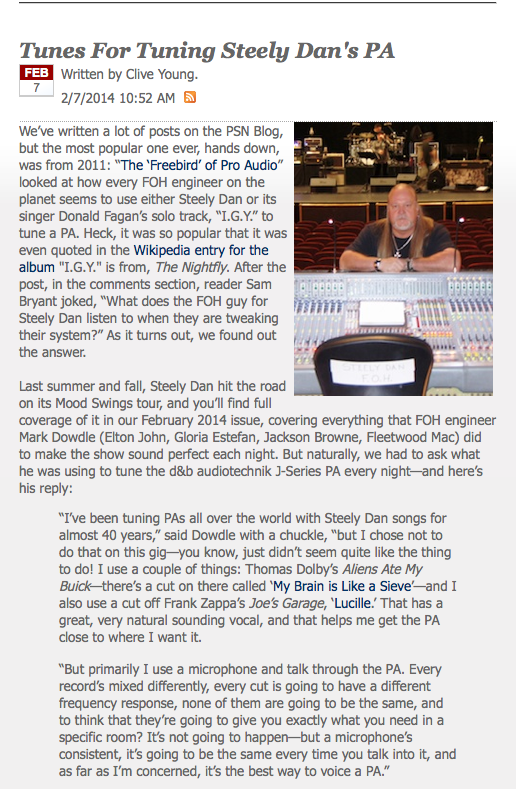
I recently ran into a fellow sound engineer who works with another local sound engineer who has a medium sized JBL / Cerwin rig he uses on outdoor gigs. The rig is comprised of up to (8) JBL SR4732X 3 way boxes and (8) to (16) Cerwin Vega L36 / B36 subs although this evening rig used (6) and (6).

JBL 4732 PA

JBL SRX catalog
Cerwin Vega – L36 sub

Last time I saw the rig in action was years ago and I wasn’t paying that much attention but there were only (2) mid / high boxes per side and (2) subs per side on an outdoor event. That was probably 20 years ago.

In case it’s not already quite clear, as you add more and more boxes together, your chance for phase issues goes up exponentially if they aren’t placed and splayed correctly.

POP QUIZ:

What sounds worse than a (2) box a side PA splayed wrong?

ANSWER:

A (4) box a side PA splayed wrong!

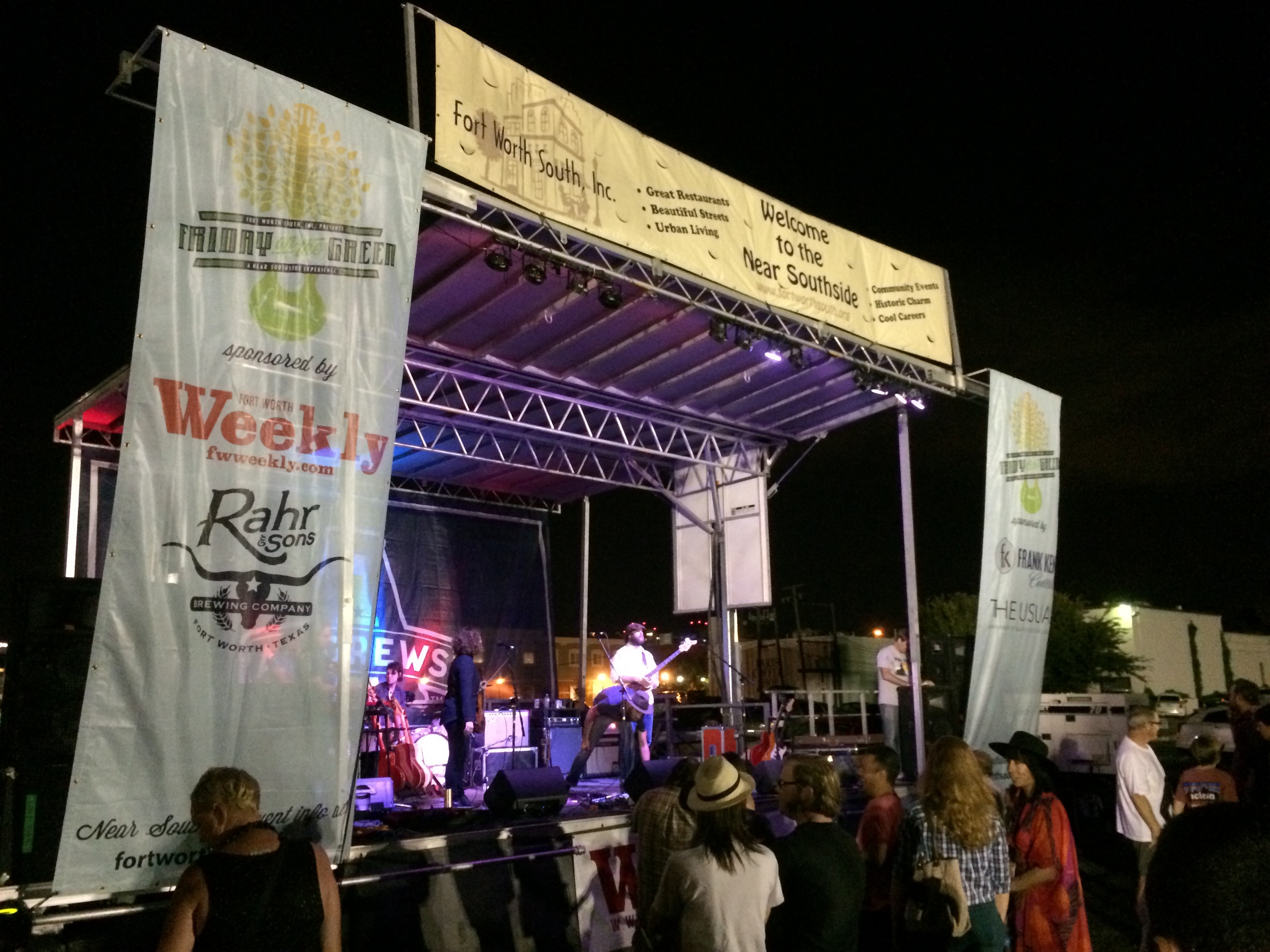
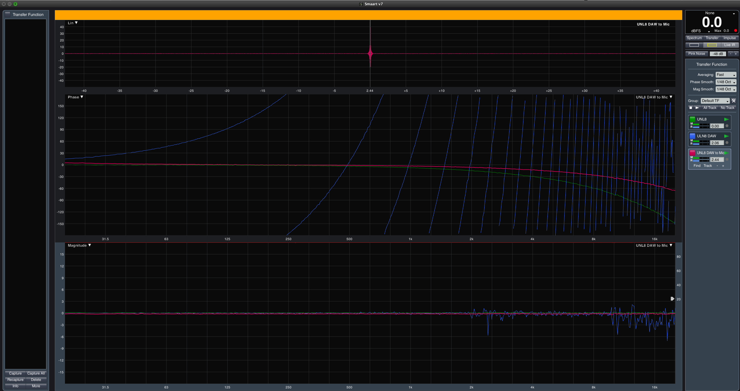
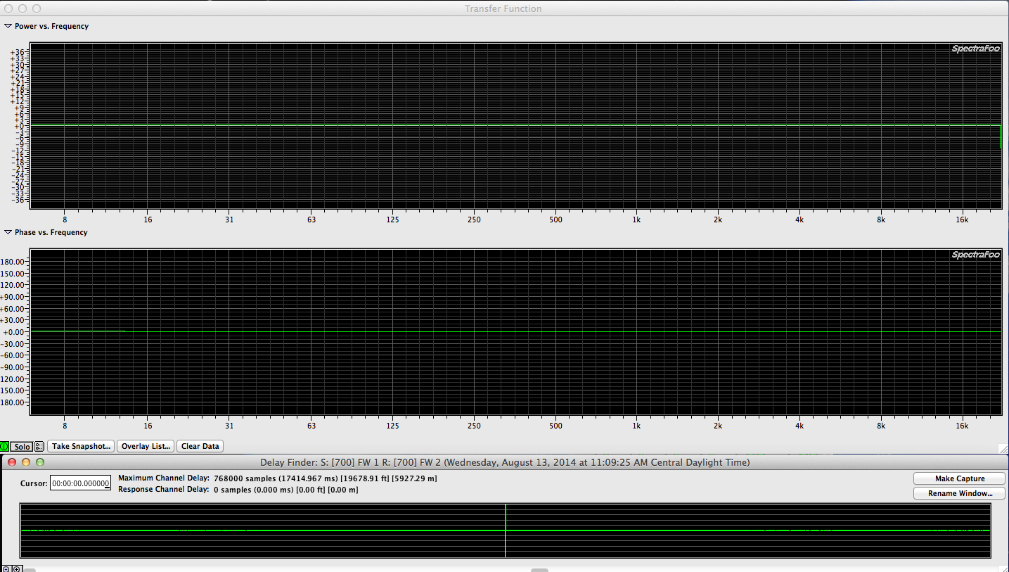
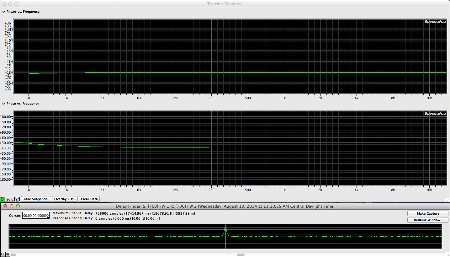
The specs for the JBLSR4732X says that the HF horn is 90 x 50. The spec sheet also reveals that there is a UHF driver that has a 100 x 100 dispersion pattern. How do you mix 90 x 50 with 100 x 100? I’m not sure but even more important, how do you put 2, 3, or even 4 90 x 50 horns next to each other correctly? There should be a splay of approximately 35 to 45 degrees between cabinets and the final splay should be based on measurements. A 90 x 50 degree horn might really be a 92 x 48 or a 88 x 51. The splay should avoid holes in frequency response between cabinets but it should avoid overlap that causes comb filtering. The cabinets (more than 1) should be delay corrected in order to line them up. Where do you put the mic to measure the delay time between (2) cabinets that are splayed correctly? That is a question I will have to answer once I have a bit more experimentation under my belt. I will ask someone who splays similar cabinets for a living and measures their response. In the meantime, here is the way the PA was configured this evening for an outdoor show.

JBL 4732 1

JBL 4732 2

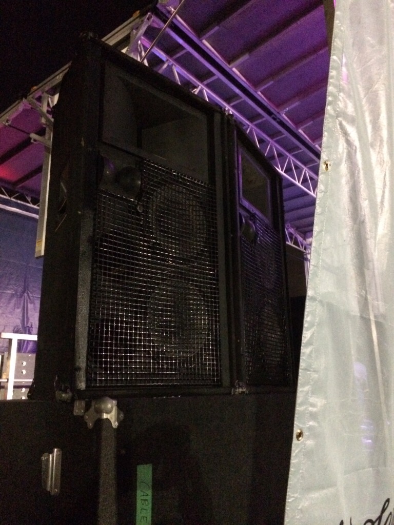
You will note that the (2) raised cabinets are “slightly” splayed but obviously not by 35+ degrees from each other. Then add in the 3rd “front fill” cabinet and you’ve basically got (3) 90 x 50 horns all aiming in the same direction.

Here is what the specs are for the MF driver:

JBL 2447J 1.5″ Titanium Horn Driver 16 Ohm

The Model 2447J is a 1.5″ exit diameter addition to JBL’s family of professional quality compression drivers. The 1.5″ exit allows the Coherent Wave™ phasing plug to directly couple with Optimized Aperture™ Bi-Radial® horns to provide lower distortion and better coverage control to 20 kHz than previous designs. In addition to improving performance, the 1.5″ exit design also reduces size and weight. The Coherent Wave phasing plug structure has four equal length passages to provide in-phase summation of diaphragm output at the 1.5″ exit. This optimized configuration produces coherent acoustical power up to much higher frequencies than more conventional designs. The diaphragm design includes JBL’s exclusive three-dimensional diamond pattern surround tuned to reduce fatigue-inducing stresses in the membrane and support structure. This provides predictable normal resonance modes, and radial reinforcing ribs increase diaphragm stiffness. This diaphragm design combined with the Coherent Wave phasing plug increases the 2447’s output in the 5 kHz to 20 kHz range.

High temperature voice coil former materials and adhesives enable the 2447J to handle high power levels over extended periods of time. The voice coils themselves are identical to previous JBL models, so that impedance and network matching will be the same. After manufacture, the frequency response of each transducer is tested for conformity to JBL’s rigid performance standards. The model 2447J is ruggedly constructed to withstand the rigors of both fixed installations and touring applications. All tolerances are held to the same high levels traditionally associated with JBL designs. The JBL manufacturing process permits the use of rim-centered diaphragms for instant interchangeability and ease of field service.

Specifications: • 100 watts continuous above 500 Hz, 150 watts continuous above 1 kHz • Voice coil diameter: 4″ • Frequency range: 500-20,000 Hz • Sensitivity: 112 dB (1W/1m on 2352 horn) • Nominal impedance: 16 ohms • Net weight: 23.5 lb. • Dimensions: 9-1/4″ dia. x 4″ depth.

Product Specifications

Mounting Type4-Bolt
Exit Diameter1.5″
Diaphragm MaterialTitanium
Impedance16 ohms
Power Handling (RMS)150 Watts

JBL 2447J 1.5″ Titanium Horn Driver 16 Ohm

BrandJBL
Model2447J
Part Number294-438
UPC844632066894
Product CategoryHorn Drivers
Unit of MeasureEA
Weight26.5 lbs.

Here are the specs for the HF driver

Professional Series
Key Features:
Bi-Radial
®
Constant-Coverage
horn design
Constant 100° x 100° dispersion
from 3 kHz to 20 kHz
40 watts continuous program
3 kHz to 21.5 kHz response
Annular-ring diaphragm ferrite
motor structure
44 mm (1
3/4
in) edgewound
aluminum ribbon voice coil
105 dB sensitivity, 1 W, 1 m (3.3 ft)
2404H
Designed for use as an ultra-high
frequency driver in multi-element,
full range loudspeaker systems, the
JBL Model 2404H delivers an un-
matched combination of wide, tightly
controlled dispersion, extended fre-
quency response, high power capac-
ity, and high efficiency
One key to this outstanding perfor-
mance lies in the unique geometry of
the driver

s Bi-Radial horn
¹
Devel-
oped with the aid of the latest compu-
ter design and analysis techniques, the
horn provides constant coverage from
its recommended crossover point of
3 kHz to beyond 20 kHz. The Bi-Radial
compound flare configuration main-
tains precise control of the horn

s
wide 100° x 100° coverage angle, and
the horn

s rapid flare rate dramatically
reduces second harmonic distortion.
The uniform coverage of the horn is
illustrated by the detailed polar data
and the isobar (constant sound pres-
sure) contours included in this speci-
fication sheet. The polar curves of the
2404 exhibit soft-edge pattern charac-
teristics, due to the gradual drop-off of
level with increasing off-axis angle.

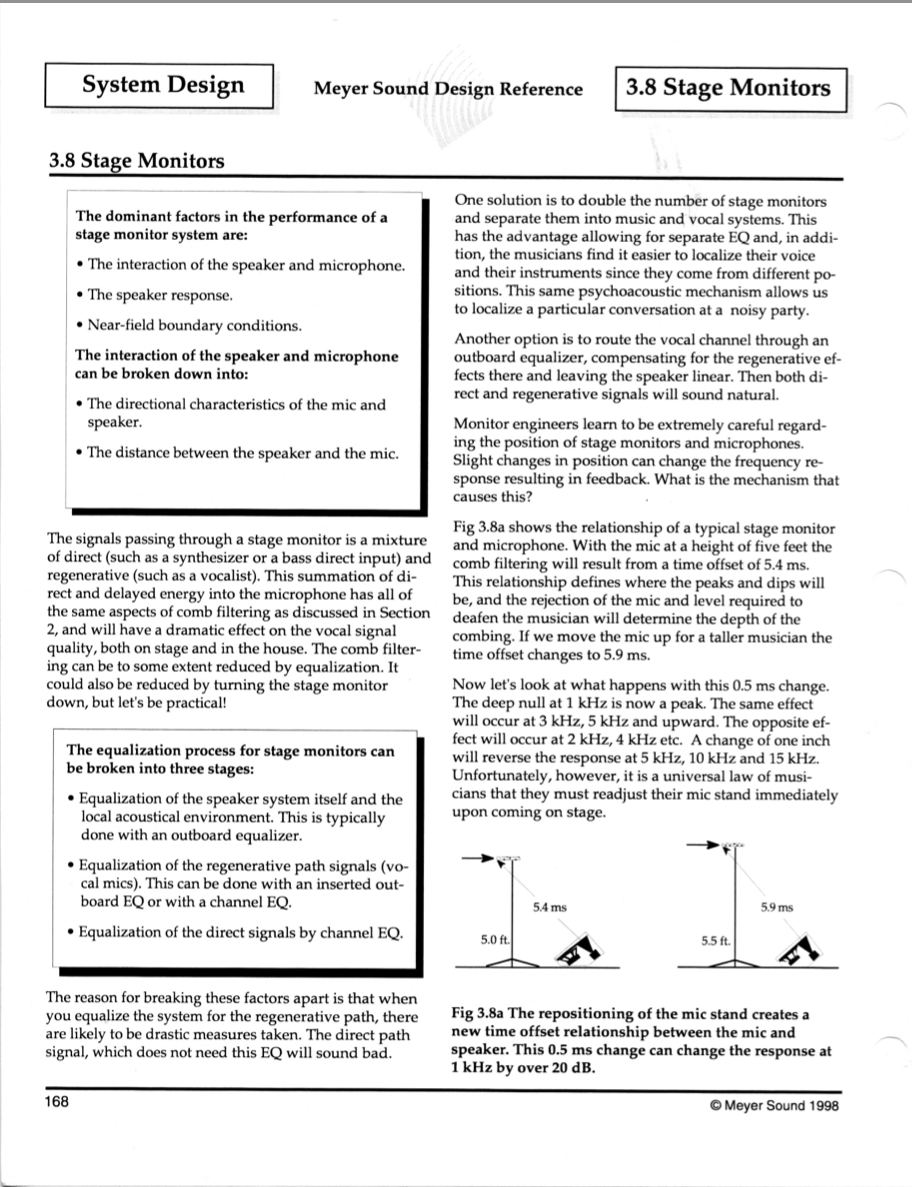
Here is an interesting thread about the JBL SR4732X boxes HF characteristics.

Live Sound Int forum – JBL SR4732X crossover quesiton (long)

Smaart 7 – multiple TF traces in the same window & Live IR

I finally got around to working with Smaart 7 long enough to get comfortable with the interface. I watched all the tutorial videos as well as read the available literature to get there.

There are (2) things that Smaart 7 can do that in my opinion are worth the price of admission.

Multiple transfer functions (as many as your hardware can handle)
LIVE IR – (Live Impulse Response)

In the case of being able to show multiple TF traces in the same window, this allows for realtime view of a setup like the following:

TF 1
REFERENCE SIGNAL – audio interface output
MEASUREMENT SIGNAL – console output

TF 2
REFERENCE SIGNAL – console output
MEASUREMENT SIGNAL – DSP output

TF 3
REFERENCE SIGNAL – DSP output
MEASUREMENT SIGNAL – Measurement mic

Or for a large setup using multiple mics, maybe something like this:

TF 1
REFERENCE SIGNAL – audio interface output
MEASUREMENT SIGNAL – measurement mic 1 / FOH MAIN

TF 2
REFERENCE SIGNAL – audio interface output
MEASUREMENT SIGNAL – measurement mic 2 / FRONT FILL

TF 3
REFERENCE SIGNAL – audio interface output
MEASUREMENT SIGNAL – measurement mic 3 / UNDER BALC

TF 4
REFERENCE SIGNAL – audio interface output
MEASUREMENT SIGNAL – measurement mic 4 / OVER BALC

TF 5
REFERENCE SIGNAL – audio interface output
MEASUREMENT SIGNAL – measurement mic 5 / DELAY

TF 6
REFERENCE SIGNAL – audio interface output
MEASUREMENT SIGNAL – measurement mic 6 / LOBBY

Here is a screen shot of (3) overlapping measurements in Smaart 7. Green, Blue and Pink. These are just junk measurements but the concept is sound. You can see everything you’re interested in knowing on the same screen at the same time and watch as you make adjustments system wide (if you’ve got enough measurements going). I don’t think the importance of this can be overstated.

Smaart 7 - 3 TF measurements active

What is so cool about the LIVE IR window? Without the LIVE IR window, every time you move the mic or adjust a delay time, you might have to FIND the delay offset time again. With LIVE IR, it constantly updates the impulse response. I’ll give you an example of where this could be really helpful.

Let’s say you want to ring out 12 wedges on stage and your measurement rig is at FOH. You feed pink noise down a return line to the monitor console. Now you can send your REFERENCE SIGNAL to each stage monitor. With LIVE IR, you don’t have to run back and forth between FOH and the stage to FIND DELAY.

On a recent show, I used the venue projectors to project my measurement window onto all the screens in the room. This way I could see my measurement window from the stage on 10’x14′ screen! Live IR would of saved me a lot of time.

Avid Audio Splitter – stereo XLR splitter box

I’ve been looking at XLR Y splitter boxes for my measurement rig for some time and when I saw a stereo Avid Audio Splitter listed on EBAY, I ordered one. The cost was around $20 and I couldn’t build one for much less than that (ignoring labor). I didn’t know what to expect inside the box but there is no power connection so the device is obviously passive. Regardless of the circuitry, I could modify the box if necessary. The device has the following connections:

LINE IN (Left / Right)
LINE OUT (Left / Right)
MONITOR OUT (Left / Right)

Avid Audio Splitter connections

Of special interest is the massive metal piece inside the box that serves no purpose other than to add weight to the device. Everything else is plastic so it must of been decided to add the weight to keep the box from falling over from the weight of (6) XLR connectors. Counter ballast if you will.

I checked the circuit board and the LINE IN to LINE OUT connections are parallel connections (straight wire). I had hoped that the MONITOR outputs were also parallel connections but instead there are some passive components involved in that signal path.

Avid Audio Splitter inside

Here is the trace when I measure the LINE IN to LINE OUT path. Note the perfect impulse response as well as perfect frequency and phase response. What we would expect from a piece of 3 conductor wire with connectors on the ends compared with another piece of 3 conductor wire with connectors on the ends.

Screen Shot 2014-08-13 at 11.10.01 AM

What do the resistors and capacitors do in the MONITOR OUT circuitry? Here is a trace of the LINE IN to MONITOR OUT path
Screen Shot 2014-08-13 at 11.10.41 AM

Together, the capacitors and resistor networks cause an 18db reduction in gain and some low end phase drift (due to the capacitors). The capacitors also appear to elongate the impulse response. Certainly not what I want to use as a reference point!

Here is a overlay of all (4) snapshots. Left / Right traces match but there is the same -18db reduction in gain.
Screen Shot 2014-08-13 at 11.13.43 AM

Since the goal is to have a stereo 1×2 splitter box with parallel connections, I’ve installed some wire jumpers across the LINE OUT and MONITOR OUT XLR pins which in theory will bypass the resistors and capacitors.

Avid Audio Splitter jumped

Here is a measurement overlay between the original LINE OUT and the MONITOR OUT with the jumpers installed between LINE OUT and MONITOR OUT pins. Identical.

Screen Shot 2014-08-13 at 11.03.36 PM

Now I’ll install permanent jumpers between the LINE OUT pins and the MONITOR OUT pins and put this box back together. I’m using buss wire which is solid and relatively non flexible for the connections.

buss wire

I’m also using clear shrink wrap to avoid any shorts. I shouldn’t need it if I bend the buss wire correctly but I have the shrink wrap and it can’t hurt:)

shrink

Here is the device with (6) buss wires installed.

Avid Audio Splitter complete mod

Let’s measure again to verify we have achieved the desired goal.

Screen Shot 2014-08-14 at 8.45.08 PM

(4) snapshots that overlay perfectly. I’m going to put the device back together and move on…

Smaart I-O

Smaart IO front large

Smaart IO back large

Details

The Smaart I-O is a measurement grade 2×2 USB audio interface designed and built specifically for use with Smaart v7 Measurement Software. The I-O features two high-quality, active balanced inputs with 50 dB of computer adjustable gain in precision 1 dB steps. These input gains are monitored directly by Smaart allowing the user to retain accurate SPL calibration while varying measurement signal input levels.

The inputs employ a Neutrik combo jack (XLR / ¼”) to accommodate both mic and line level input signals, each with switchable 48V phantom power on the XLR inputs for measurement mics and a 20 dB pad on the ¼” to accommodate line level signals. The Smaart I-O also features two active balanced XLR outputs capable of providing +8.2 dBu (2 Vrms) max level signal for playback or excitation sources.

Powered by the USB port of your computer (or via the optional 5 VDC jack), the Smaart I-O provides a compact and portable measurement-quality input for your Smaart rig.

A simple control program, included with the product on CD-Rom (or available via download from our website) sets preamp gains and phantom power selection, and automatically integrates with Smaart v.7. The control program also provides firmware update capability and can rename the Smaart I-O at the hardware level – an important feature when using multiple devices with Smaart.

Smaart I-O Features:

•Two (2) Neutrik XLR – ¼“ combo jack inputs:
oComputer controllable 50 dB analog gain in precision 1 dB steps
o Max input (at minimum gain): +6 dBu (XLR), +26 dBu (¼ ”)
o Active balanced with 2k ohm impedance (XLR), 65k ohm (¼ ”)

• Two (2) Active Balanced XLR Outputs
o 150 Ohm impedance o Max Output : +8.2 dBu (2.0 V rms) w/ 100k ohm load

• Frequency Response o Magnitude 16 Hz – 20 kHz, +/- .25 dB
o Phase 16 Hz – 20 kHz, +/- 10 deg

• Sample rate clocks of multiple I-O’s can be linked to allow for device aggregation in Smaart’s dual-channel measurements.

• Bus powering via USB for convenient, single-cable connection to the computer.

• Optional 5 VDC jack in cases of insufficient USB power

• Dimensions 1.75” (h) x 7.25” (w) x 4.25” (d)

© 2014 Rational Acoustics, LLC. All Rights Reserved.

FWAFA – Fort Worth, Texas

The PA system at Fort Worth Academy of Fine Arts has gone through many different stages since the venue was taken over. Originally the space was a church sanctuary with a small stage and more seats. When the church built a new building and sold the old one to the school, the PA remained AS IS. This was a bad deal because the school extended the stage which put the overhead PA behind the stage:(

At one point the over head speakers (LCR center cluster) were moved to the front of the new stage but they were still high above the audience so the imaging was 90 degrees overhead for the front row of seats. In 2011, the school purchased some QSC KW122 self powered speakers for mains and monitors and they were hung just high enough to stay clear of the FOH lighting positions. About 1/2 as high as the original center cluster.

Much better imaging, a true stereo PA for the mains & side fills, delays, subs processed by a Media Matrix Xframe 88 and (2) 8802 Break out boxes.

The house PA consists of the following:

House Left
House Right
House Left sidefill
House Right sidefill
Subs (2) under the stage
Delays (2) about 2/3 back in the house and in line with the House L/R speakers

Each of these zones is fed from a separate output on Xframe 88. The subs are fed from an Aux send via a 3rd Xframe 88 input.

Standard wireless rig for measurement purposes?

I’ve known for years that engineers who make measurements wirelessly are using a special type of wireless specifically designed or the purpose. We are told that we need a digital wireless without a compander circuit to be able to measure accurately. Fine. No doubt those that know about such things are right but I wonder what sort of problems come up with using an off the shelf wireless rig.

Since as a general rule, we use omni mics for making audio measurements the path of least resistance is to start with a wireless lapel / omni lav mic. For this experiment, I’ll be using a Sennheiser Evolution series rig.

INSERT RESULTS HERE:

SpectraFoo Transfer Functions 102 – audio interface verification

Armed with the key commands, you’re ready to zip through some measurements…

One of the first measurements I recommend performing is to measure the outputs of your audio interfaces against the inputs. This test verifies they match in gain and that there are no malfunctions. This measurement is about as simple as it can get.

(1) audio interface (two channel minimum & preferably with balanced input and outputs)
(2) patch cables (may be XLR to XLR / XLR to TRS / TRS to TRS / TRS to TS / TRS to RCA)

WARNING – IF YOU PATCH AN OUTPUT INTO AN INPUT WITH PHANTOM POWER TURNED ON YOU MIGHT BLOW UP YOUR INTERFACE!!!)

IF YOU’RE NOT ABSOLUTELY SURE WHAT THIS ALL MEANS, AVOID USING XLR CABLES AND YOU SHOULD BE SAFE (WITH THE EXCEPTION OF THE METRIC HALO 2882!!!!

This is what your setup might look like:

Firebox test rig

In this measurement process we measurement two signals passing through the same analog circuitry and D/A A/D converters. Assuming that everything is functioning and the cables are wired correctly, we are comparing identical signal paths so the measurement should be perfect. The expected measurement will have perfect frequency and phase response traces. Like this:

Firebox Out to IN

If you have a perfect phase trace but the frequency response trace doesn’t align to the 0db marker, you have a gain discrepancy. This could be due to different gain settings on the audio interface which is simple to correct & verify or you may have a patch cable that is wired wrong. In either one of these cases, the measurement might look like this.

Firebox Out In 12db

In this case, I created this gain mismatch by boosting the gain on one of the inputs. If I reverse the signal assignment settings, the phase response trace will still be perfect but the frequency response trace will indicate -12db instead of at +12db. Like this:

Firebox Out In 12db rev

If your audio interface has more than 2 channels, it would be wise to measure each one against another. As long as they all measurement exactly the same against another, you can move on to making more complicated measurements.

Foo – How analyzer data point settings affects the measurement results

Obviously measuring things wrong and then making decisions and corrections based on bad measurement information is a waste of time at best.

I was curious how the different data point (the size of the sample window) affects a measurement.

In SpectraFoo Complete there are the following options to choose from.

Screen Shot 2014-07-19 at 4.25.11 PM

In order to keep track of the difference (if any), I took a snapshot via the “TAKE SNAPSHOT” button at the bottom left side of the TF window.

take snapshot

In that same area is a button to display the snapshot overlay list.

overlay list

This is what the overlay list looks like for this measurement process.
Screen Shot 2014-07-19 at 4.29.40 PM

When you’re saving snapshots and then comparing them, it’s sometimes helpful to discontinue the measurement process and clear away any remaining data on the screen so you’re only looking at snapshots. These are the places to stop the measurement and clear the window.

TF on off

TF clear

All of the functions mentioned above can be achieved with key commands:

foo command keys

This is what it looks like when you turn off the measurement tool & clear the realtime data while showing all the snapshots.

Metric Halo – Spectra Foo crashing upon startup

Depending on your current configuration, it’s possible for Foo to update the main preference file to a state that is unstable. If Foo crashes and then refuses to reopen without crashing again, have no fear.

SOLUTION:

In OSX versions prior to 10.9, your library is located:

In Mountain Lion (10.9), your user library is hidden from you by default. Hold the option key while choosing the “GO” menu in the Finder, and choose “Library” from that menu.

Library

Proceeed to:

Library/Preference/SpectraFoo Preferences

Preferences

Proceed to:

SpectraFoo Preferences

Once inside the “SpectraFoo Preferences” folder you will find a file called:

SpectraFoo Prefs

Put that in the trash, empty and restart Foo.

SpectraFoo Preferences without Pref file

There is no reason to delete the folder & the other files unless you are having issues while successfully running SpectraFoo which may be caused by another preference file. Once you restart SpectraFoo, the app will create a new SpectraFoo Pref file and things should be stable. Note that any chances you had made to Foo will be lost so it’s a good idea to make a copy of your SpectraFoo Preferences folder once you have things all configured to your liking.

Part of the magic of Foo is being able to make Window Sets and be able to move between custom screen layouts with keystrokes but I’ll cover that in another post.

SpectraFoo – initial setup

When you start SpecraFoo for the first time, there are some configuration duties that must be completed before the system is ready to use.

rationalacoustics.com forum thread – Generator use in Smaart 7.4

Generator Use in 7.4
Quote:
“Transfer Function measurements can also be referenced internally to Smaart’s signal generator by enabling “Allow Multi-Device Transfer Function” option on the Transfer Function page of the main Options dialog and selecting the Generator as your reference signal source. In practice there are a few caveats to doing this, again mainly associated with delay times. For one thing, the latency of the measurement system from the output to the input becomes a factor in measuring absolute delay times. (This is generally not a factor when actively recording both input signals.) Another is that the latency through the measurement system may not be consistent from one measurement to the next, meaning you may need to measure the delay again each time you stop and restart the measurement and/or the signal generator. And finally if the measurement signal input and the output used to stimulate the system under test are not identically clocked, then the reference delay time will be subject to drift while measuring, and not just when restarting the measurement.”

Overwhelmed?

After spending a few months gathering, cataloging & regurgitating the information on this site, I realize that it might all be a bit overwhelming for a visitor. Welcome to my world! I am probably on my 10th+ attempt to read & comprehend Bob McCarthy’s book “Sound Systems: Design and Optimization”. Each time I understand a little bit more. I’m going to assume that if I don’t give up, I’ll get there.

If nothing else, watch the youtube videos available on the VIDEO page. I’ll be adding more links & possible producing some in house.

Write if you have questions.

How random is your pink noise generator?

Until I read this , I hadn’t really thought about the randomness of pink noise but now I will have to find out more…

ACO Pacific – Extremely Random pink noise generator

“Many computer generated noise sources utilize 16 bit registers with 32 kHz sample rates. The resulting 2 second pseudo-random cycle has a limited bandwidth – typically 50 Hz to 16 kHz and the repeated 2 second “fold-over” of the registers produce a measurable “click” – a source of measurement error often requiring averaging 10’s or 100’s measurements. The 3025 has a useful bandwidth of 1.6 Hz to 39 kHz with 119 uHz line resolution.”

How random is software based pink noise generated in Smaart, Spectra Foo, etc…? What about hardware based pink noise generators?

Audix TM1 mic & Lectrosonics TM400 kit – RF issue

Rational Acoustics forum thread regarding an issue using the Audix TM1 mic & Lectrosonics TM400 RF kit together

Here is a quote from this thread:

Sound Forum thread about the Audix TM1 / Lectrosonics TM400 kit – RF issue

QUOTE:

Karl Winkler
04-13-2012, 12:02 PM

I know I have asked this before but…. can the TM400 work with an audix TM1 ? or do you still need a small extension cable to break up the RF issue ?

At present, the same problem still exists between the TM1 and the HM transmitter (along with the older UH400TM transmitter). We have reached a standstill mostly because both engineering teams feel that their product is not the issue (ahem…) so yes, a short cable changes the RF properties of the combination so that the problem is reduced to the point where it is usable.

END QUOTE:

It appears that a short XLR cable between the Audix TM1 & the transmitter resolves the issue.

Omni versus Cardioid for measurements

Why must one use an omni mic instead of a cardioid mic? After all, we all own cardioid mics but it is uncommon to own an omni.

The most popular (2) mics ever invented are the Shure SM58 vocal mic & SM57 instrument mic. Both have cardioid pickup patterns.

Wouldn’t it be swell to just one one of those?

Let’s take a look.

INSERT RESPONSE OF SM58
INSERT RESPONSE OF SM57
INSERT RESPONSE OF OMNI X

What would happen if we used an SM57 (the flatter of the two Shure mics) to tune a sound system?

INSERT SIDE BY SIDE TRACES

small diaphragm versus large diaphragm

One of things you will notice when looking for a measurement mic is that there are no “LARGE” diaphragm options. When it comes to reproduction accuracy, the smaller the diaphragm the more accurate it can reproduce sound.

Here is a great article by DPA that explains why.

DPA University – Large Versus Small Diaphragm article

As a side note, over the years, I have heard engineers who favor large diaphragm mics suggest that one of the reasons is because a large diaphragm mic can reproduce lows better. This is simply not true. It IS true that cardioid mics suffer from what is called “PROXIMITY EFFECT”:
WIKI – Proximity Effect

I would argue that if you want “accurate” low end response, nothing can compete with a small diaphragm omni. One example is the Earthworks M50 with a frequency specification of (3hz to 50khz +1/-3dB)!