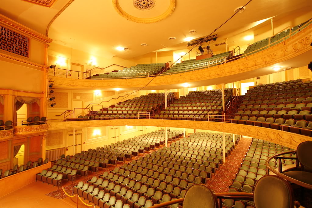
The Miller Symphony Hall is an interesting venue. Starting out as a farmers market and becoming a theater in 1899, it was one of the leading burlesque halls in the US in the early 1900s.

WIKI – Miller Symphony Hall
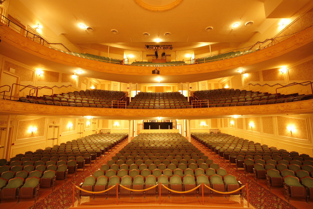
Miller Symphony Hall
Some history about the venue
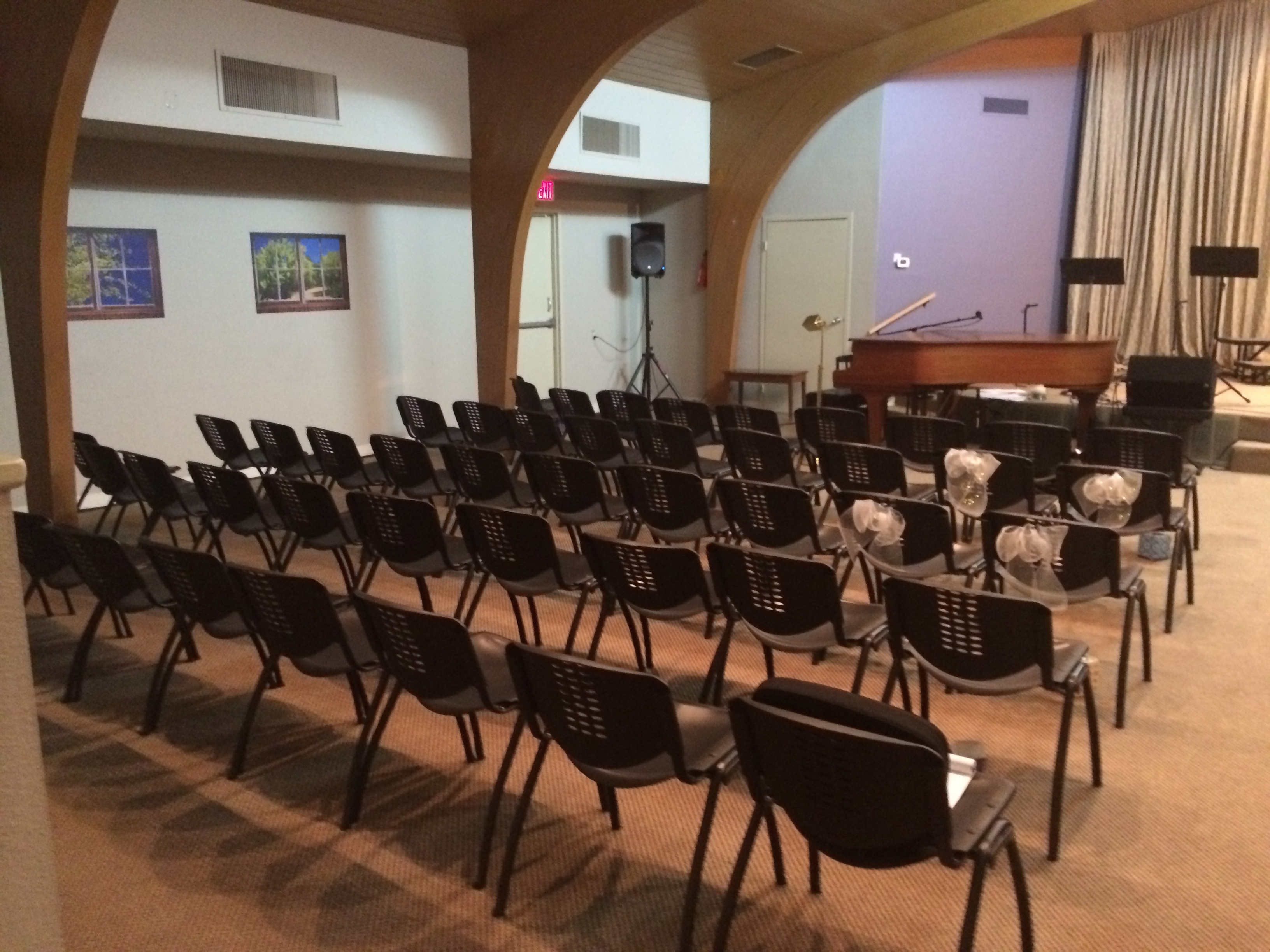
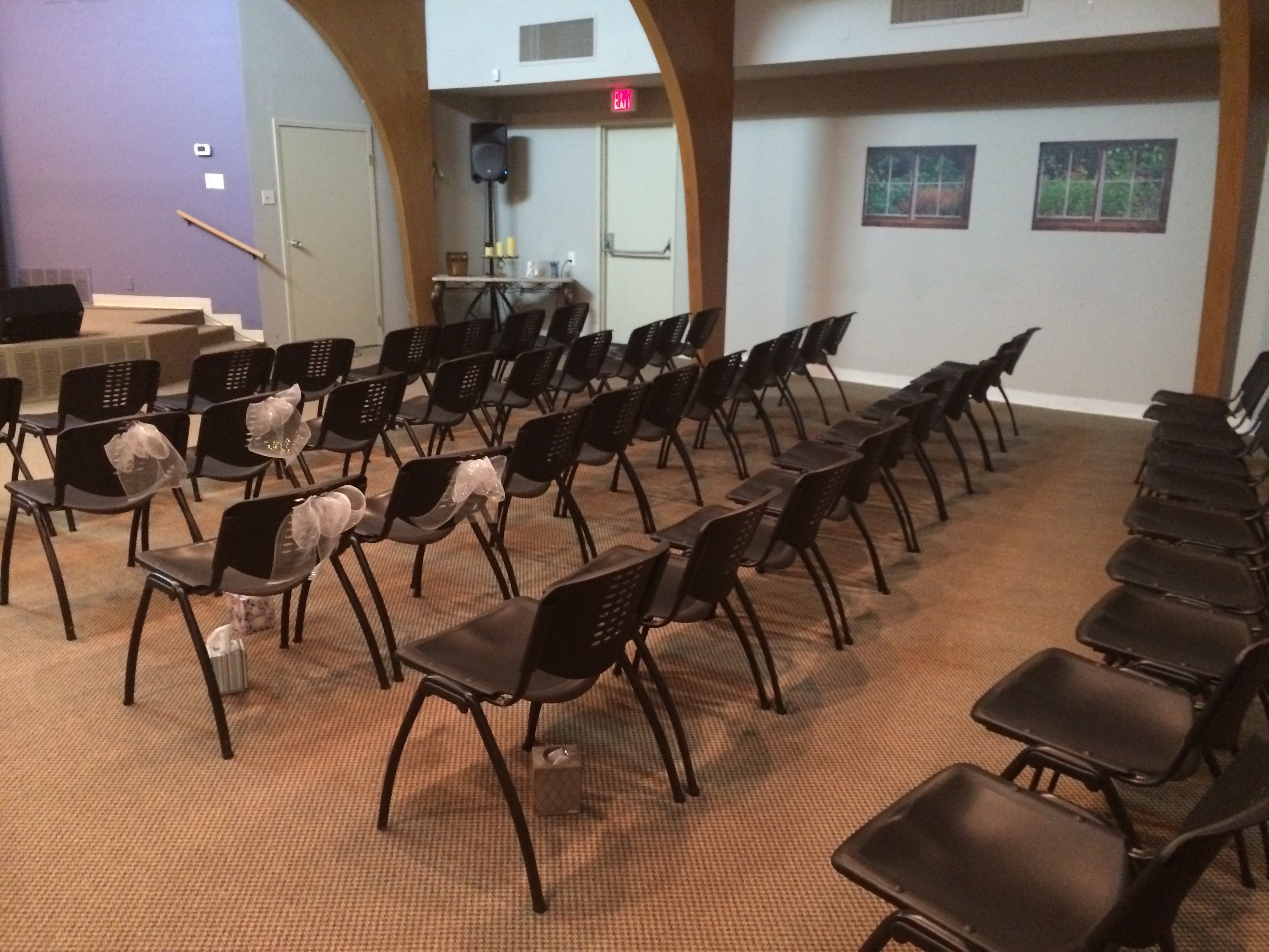
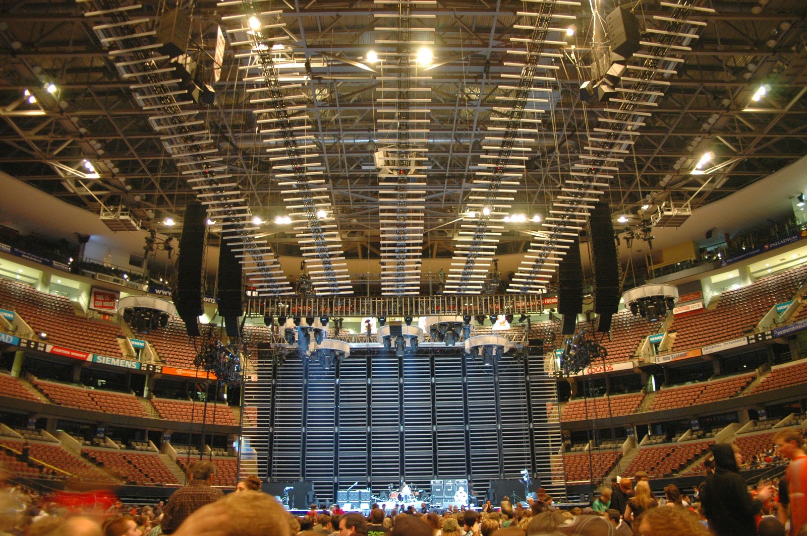
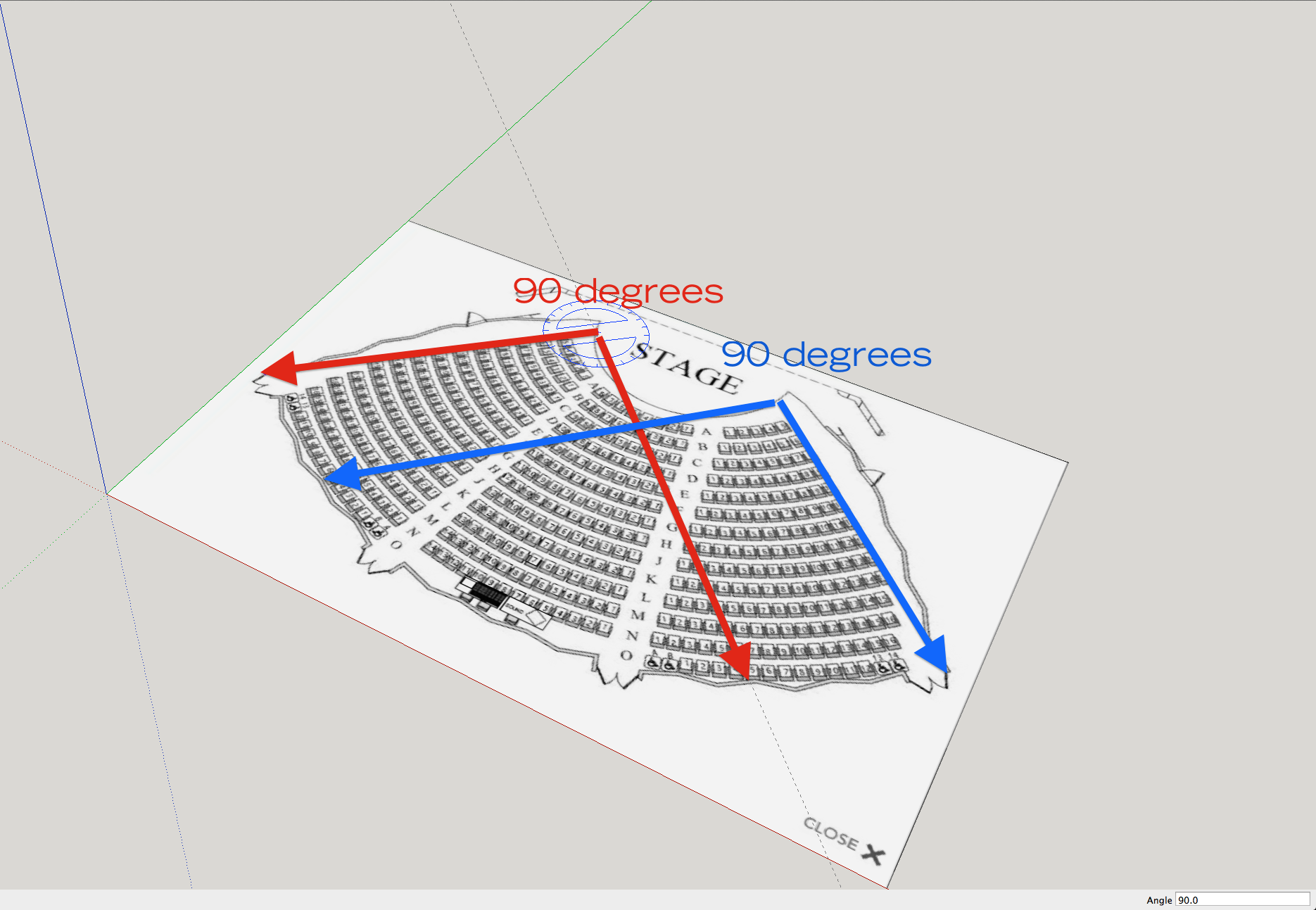
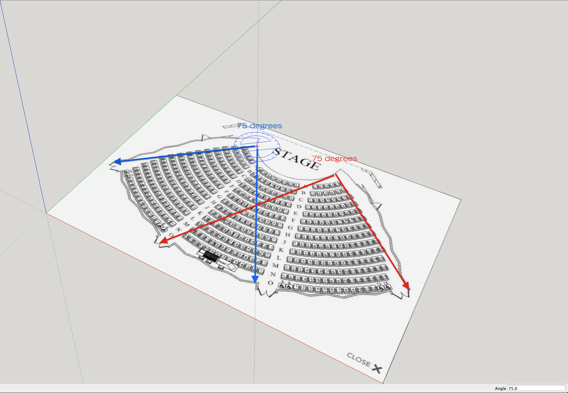
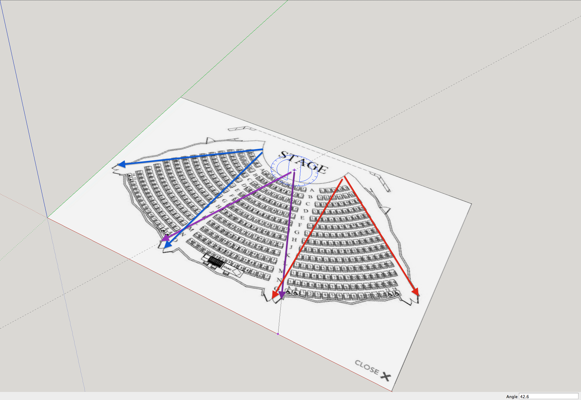
As the photos above reveal, in addition to the orchestra level, there are (2) relatively deep balconies. There are no rigging points to hand a PA over the stage. Consequently my biggest challenge was no running the PA too loud for those up close. Anytime you have a ground stacked or stage stacked PA, the people up close to the stage are going to be subjected to excess volume if the level is at show volume in the rear of house seats. That is physics and there is no way around it. Ideally a main PA is flown which evens out the volume discrepancy. In the case of the Miller Symphony Hall, there are no rigging points.
What to do? We would need to under balcony speakers and over balcony speakers to allow us to turn down the main PA and make up the different. This may actually be possible thanks to the lighting positions at each level.
My ultimate goal is never to hurt anyone ears and to avoid sound complaints. I’d rather get a “it’s not loud enough” complaint than “it’s too loud” complaint. In this case, I went out of my way to make sure the symphony and venue staff understood my concerns, understood what I could and couldn’t do and to know that I was receptive to any complaints at any time. I even met with the head ushers to explain what to expect and what to do if someone complained.
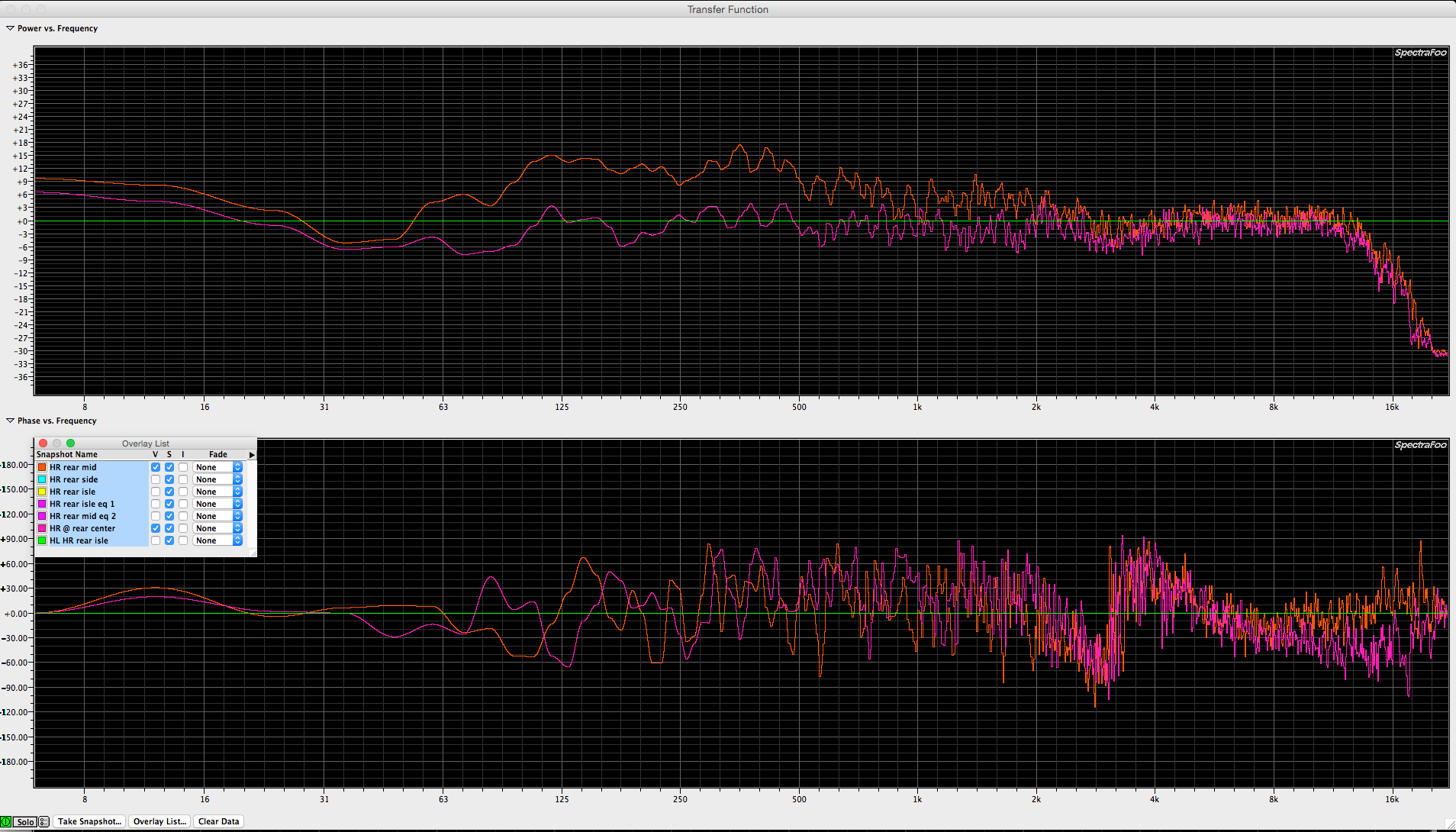
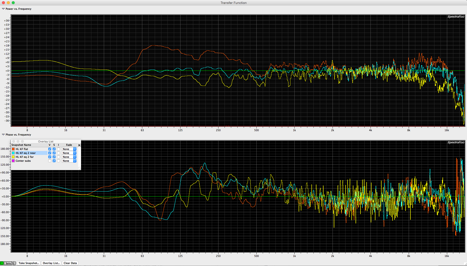
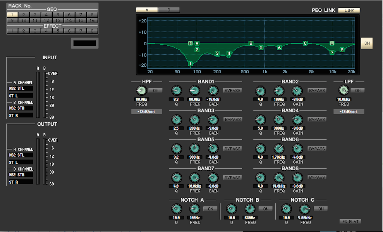
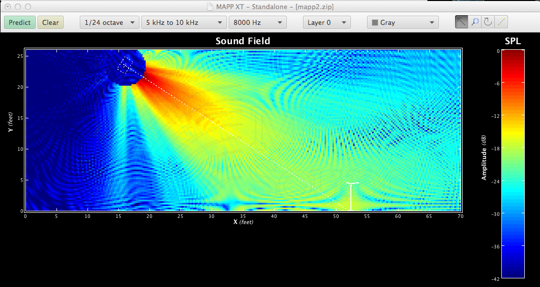
The fact that wasn’t a single reported sound complaint can be attributed to a few things. A PA that was optimized for the room (linear frequency response to the best of my ability) and the choice to leave everything a little on the dull side where I was standing. It’s counter intuitive to mix where you can’t really hear clearly what is going on but that was necessary in this case. I made probably 50 trips to the front row orchestra level to get a sense of how my mix would translate up close to the PA during the band sound check and orchestra rehearsal. Two things were obvious issue. Loud up close compared to the mix position and more present. So over the course of the sound check and orchestra rehearsal, I cut some 3150k from pretty much every channel. In hind site, I could of done the same thing at the stereo L/R buss but I never know what is needed when I start and after a while I’ve tweaked everything at the channel. Fine. More important to get through the rehearsal process and be ready for the show than to second guess every choice that is made along the way.
A few things that made the show work. First was the use of IEMs by (3) of the (4) band members. The 4th band member used hot spots which are great because they sit on a stand at chest height so they don’t have to be very loud. They also don’t reproduce a bunch of low end so there is no inherent mush involved.
There is never enough rehearsal time with the band. There is never enough time with the orchestra. How does one deal? I keep on working until I know I’ve resolve the issues I know are going to pop up. After the band and most of the orchestra left the building, a first violinist came back to practice. I politely went up on stage and said, “if you’re going to play, will you put your mic back on so I can tweak your channel?” He said sure. He probably played solo violin for 30 minutes which gave me a really good chance to walk around and listen and fine tune the EQ on his channel. A trombonist also returned and I got to work on his channel which needed some work. Lastly the harp player came back and she played for probably 30 minutes. Another rare opportunity to adjust her channel. Harps are a hard instrument to manage. They can be overly percussive at times and overly soft / dull sounding too. They can play very low in pitch and play very high in pitch. Consequently, a harp is one of the instruments I need the most time with (if I can get it). Those (3) musicians serendipitously made my job easier and made the show sound better. Thank you!
The other thing I did was spend the remaining time until dinner reconfiguring the custom layers on the Yamaha CL5 console (my favorite new console). I made a few poor decisions when building the input list which came back to haunt me. Using the custom fader layers, I was able to correct those to some degree. I was also able to setup some custom layers for a few specific songs that require some faders being close. For “Yesterday” I have (6) active channels.
Violin 1-1
Violin 2-1
Viola 1
Cello 1
acoustic guitar
Paul vocal.
I used a custom fader layer to put those channels side by side.
For Eleanor Rigby, I build a custom fader layer as follows:
V1-1
V1-2
V2-1
V2-2
Va 1
Va 2
Cello 1
Cello 2
Paul
George
Ringo
John
Custom fader layers allowed me to mix a show I didn’t really have mastered without making any major mistakes.
The Yamaha CL5 is cool in the fact that you can add channels or DCA to a custom fader layer. Very flexible. If you haven’t spent any time with a Yamaha CL or QL console, you owe it to yourself to try them both. Every console has it’s benefits and downsides. Yamaha did a good job with the CL and QL series. My only wishes would be a higher channel count (96 please instead of 72) and 24 DCA instead of 16. Seems selfish of me but that is what I need to do this gig well.