Why must one use an omni mic instead of a cardioid mic? After all, we all own cardioid mics but it is uncommon to own an omni.
The most popular (2) mics ever invented are the Shure SM58 vocal mic & SM57 instrument mic. Both have cardioid pickup patterns.
Wouldn’t it be swell to just one one of those?
Let’s take a look.
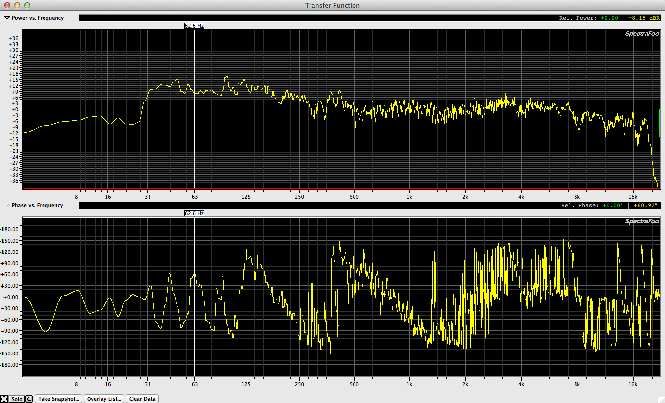
INSERT RESPONSE OF SM58
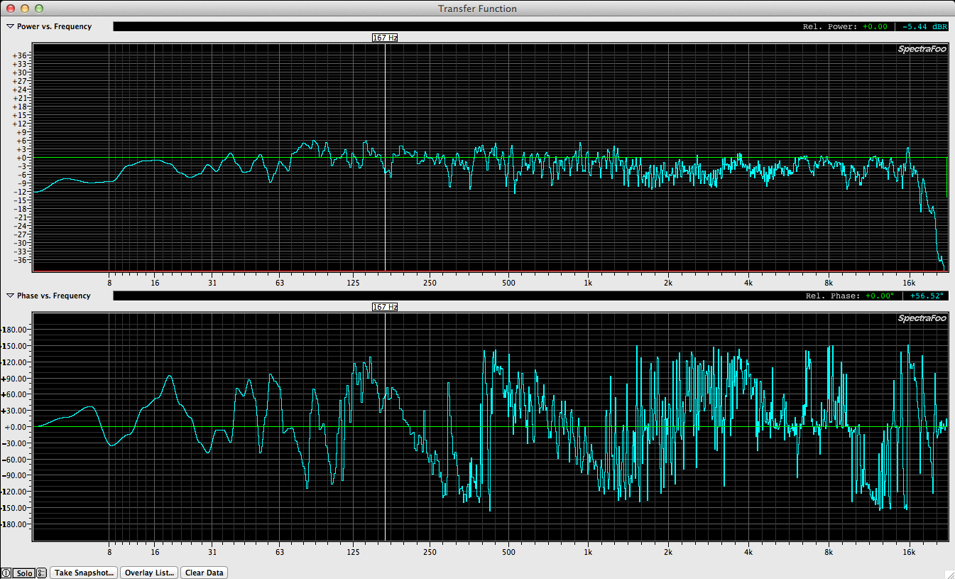
INSERT RESPONSE OF SM57
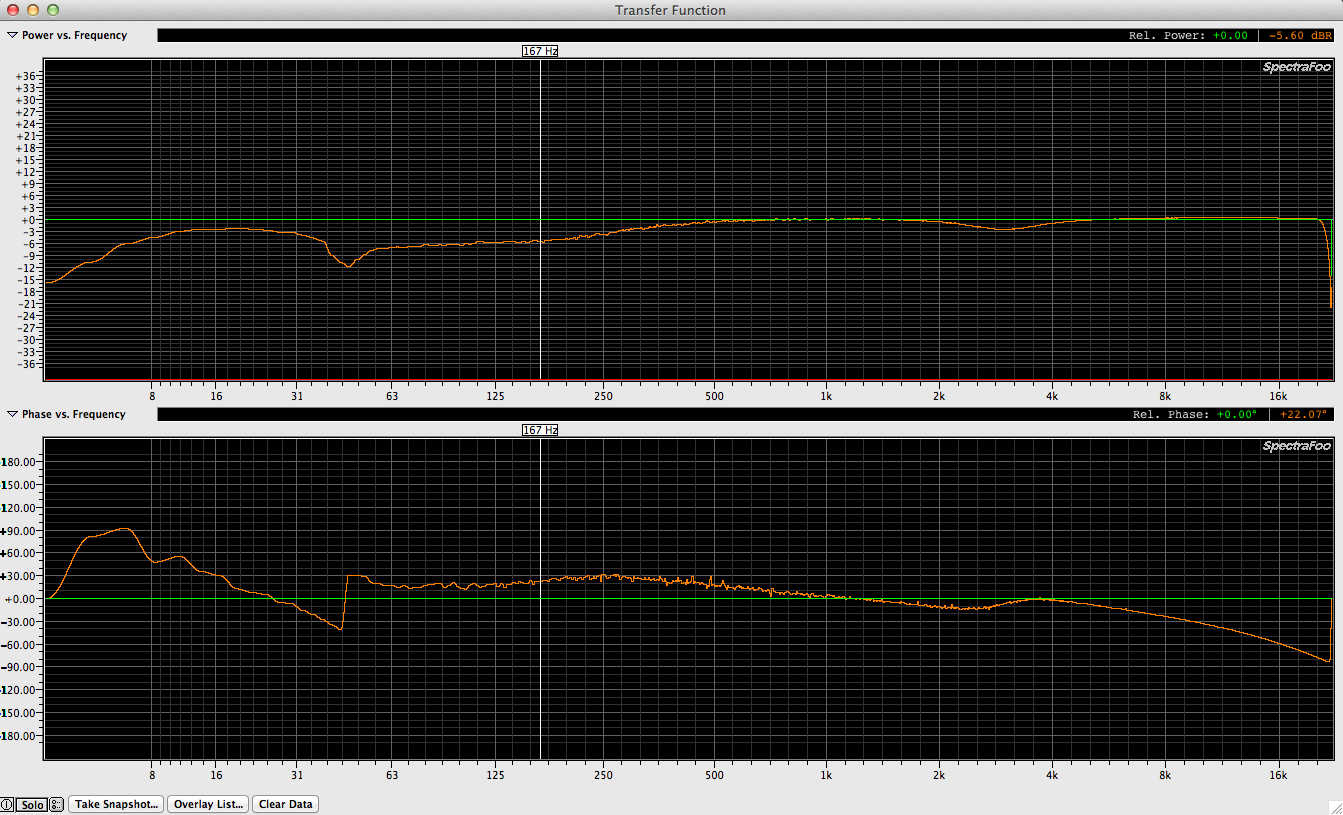
INSERT RESPONSE OF OMNI X
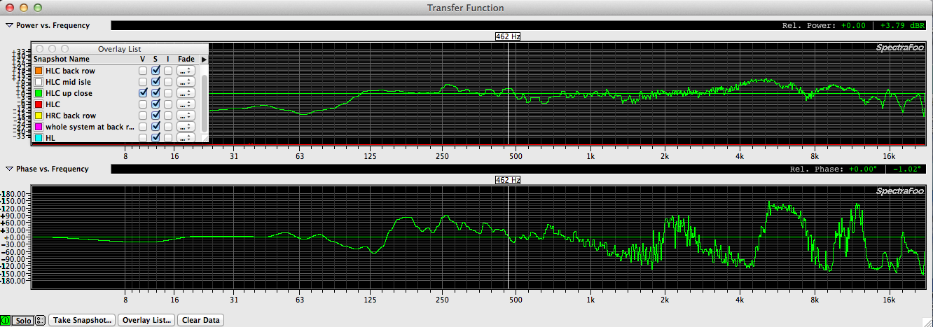
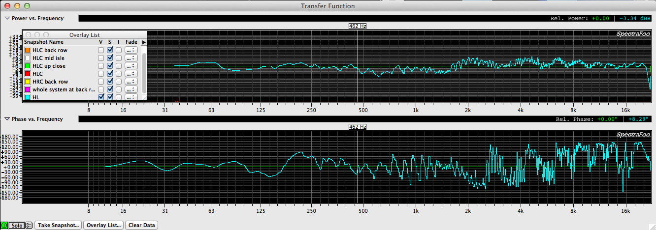
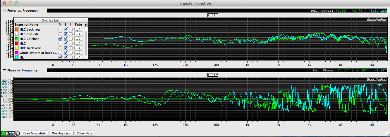
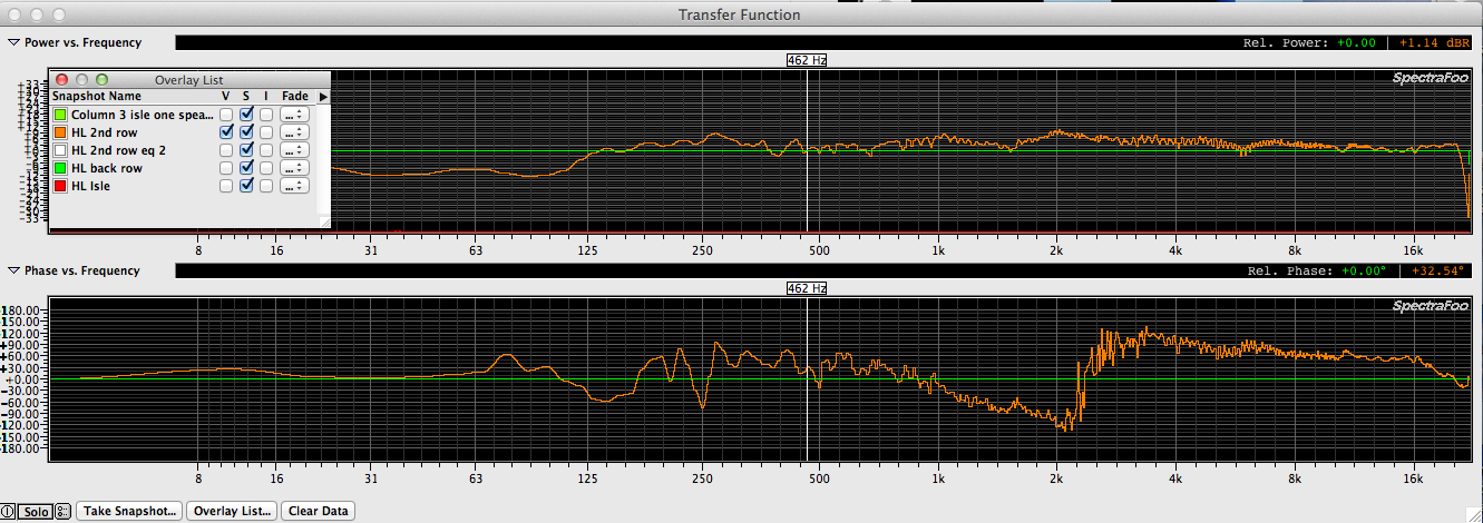
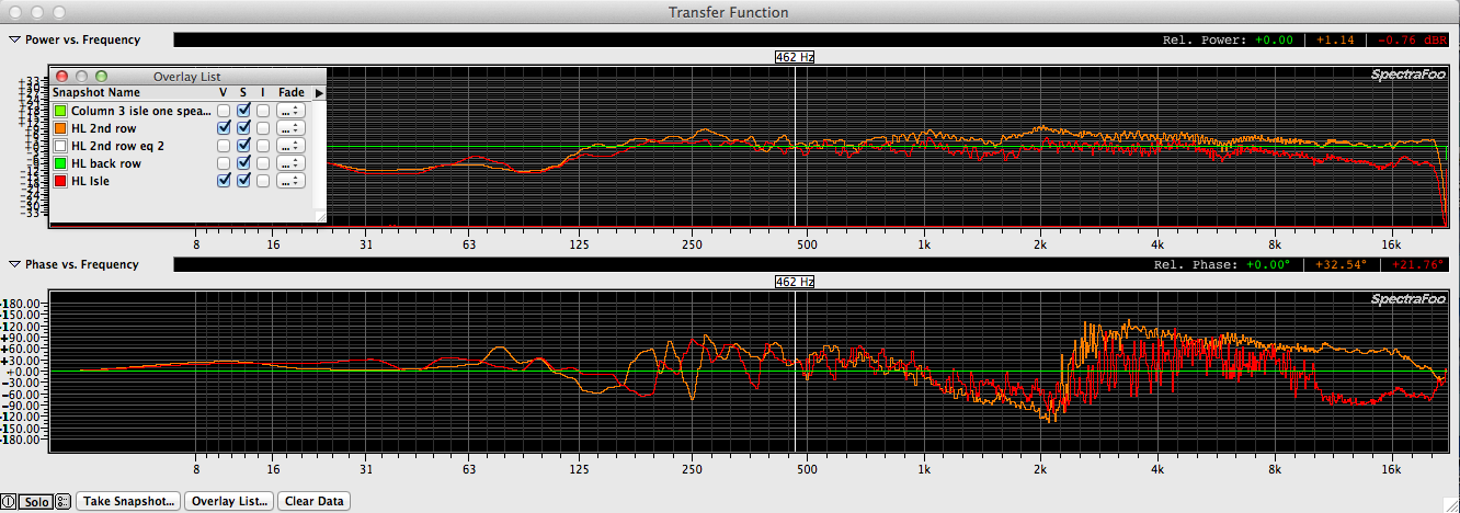
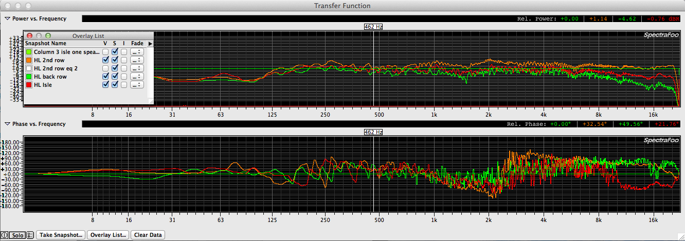
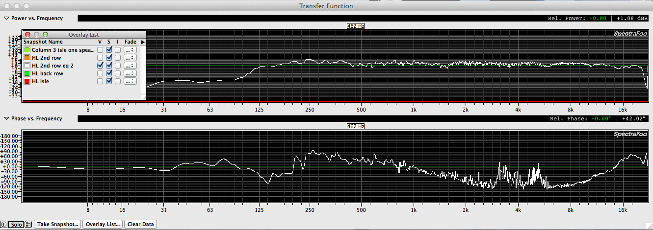
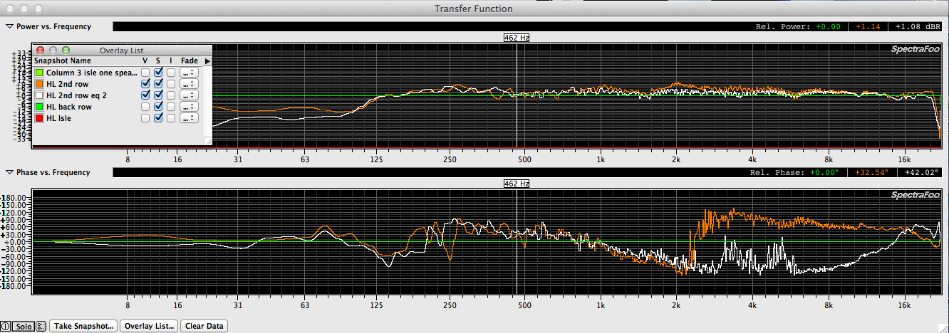
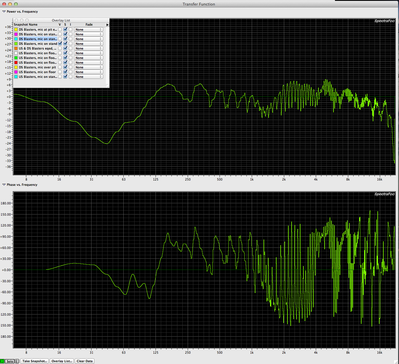
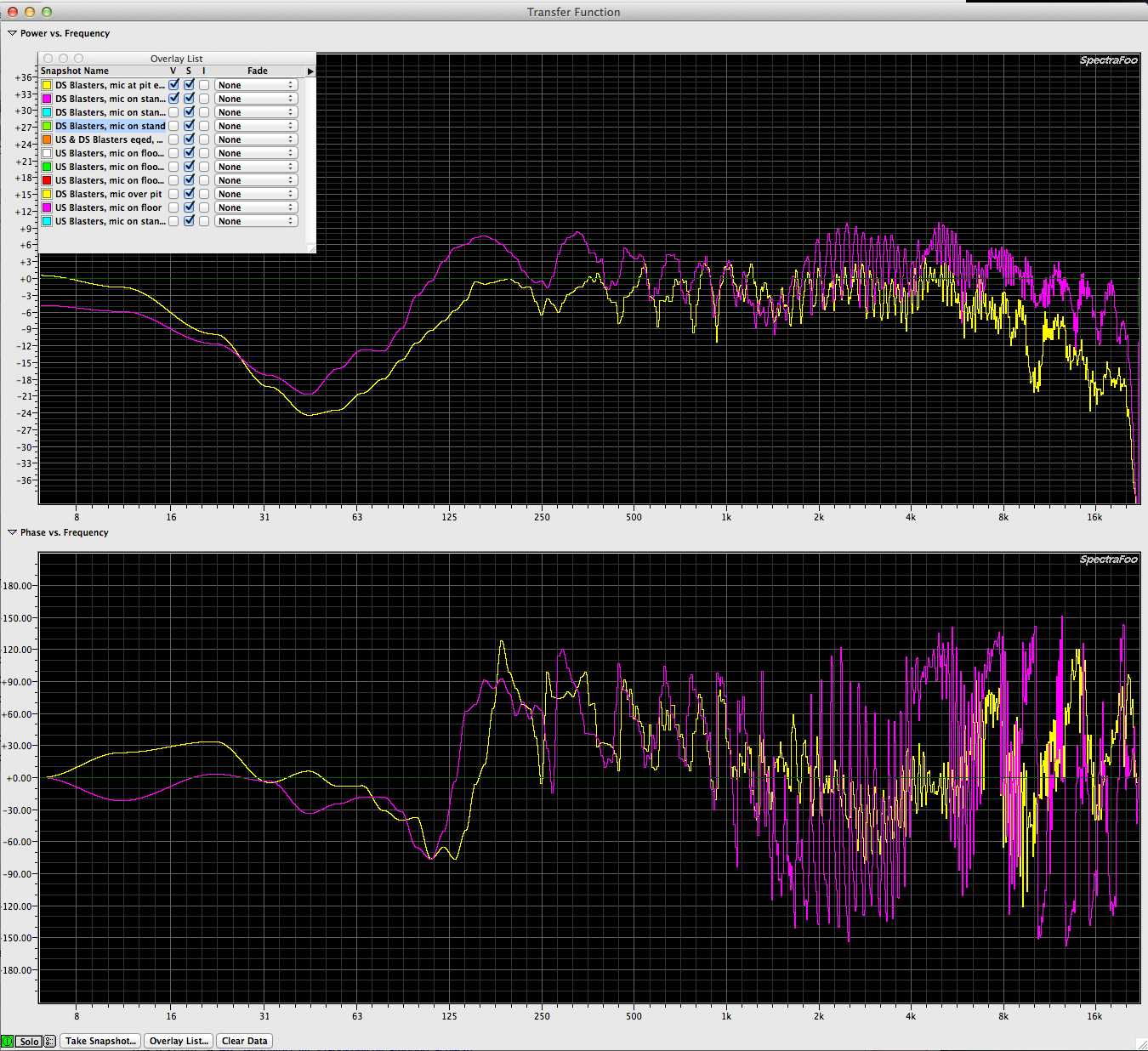
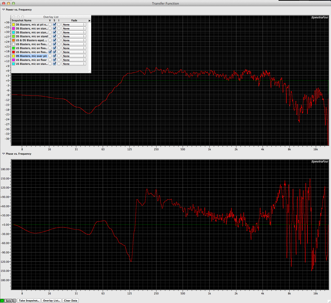
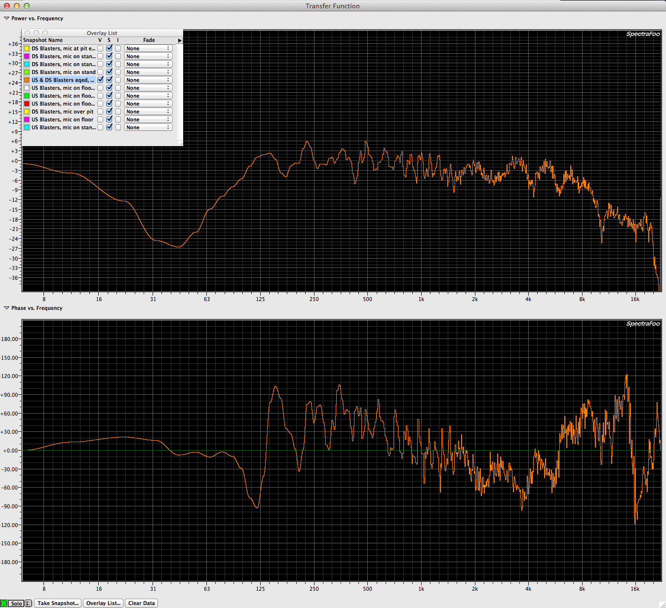
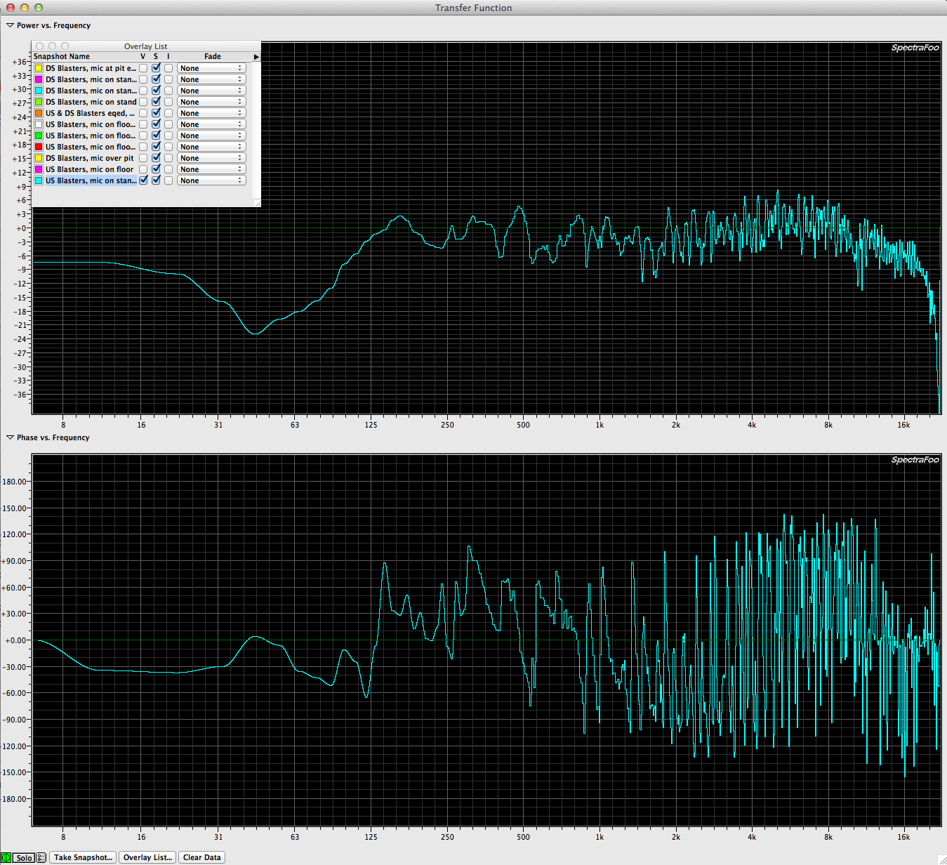
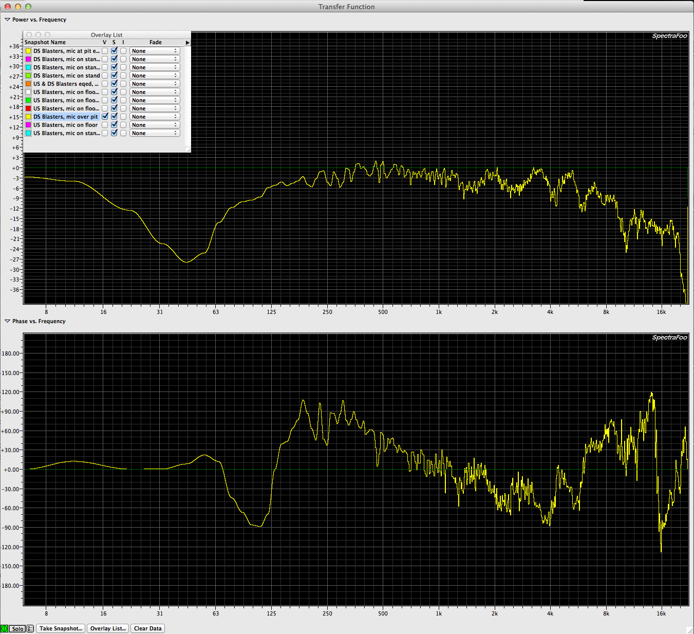
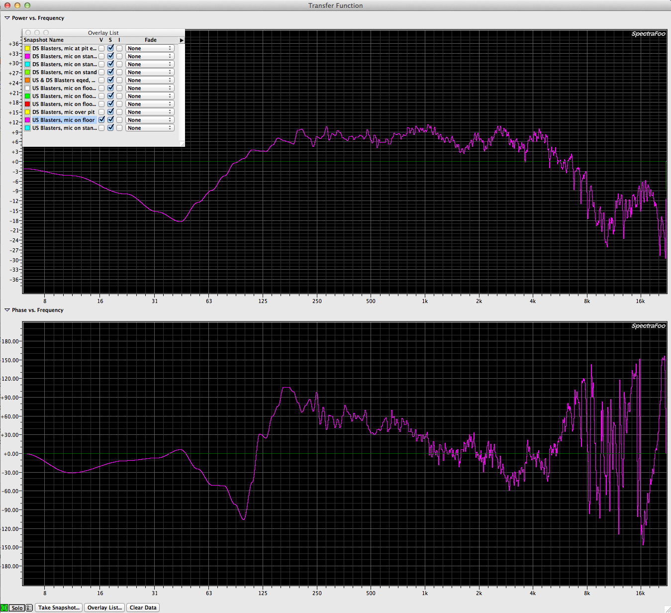
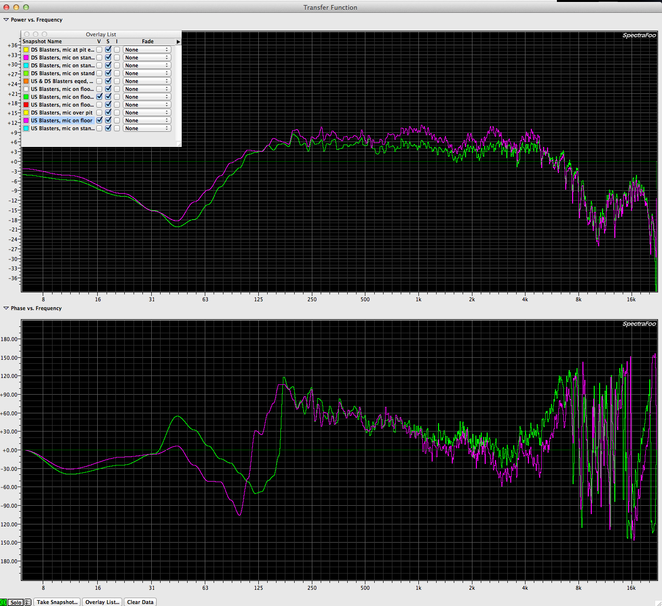
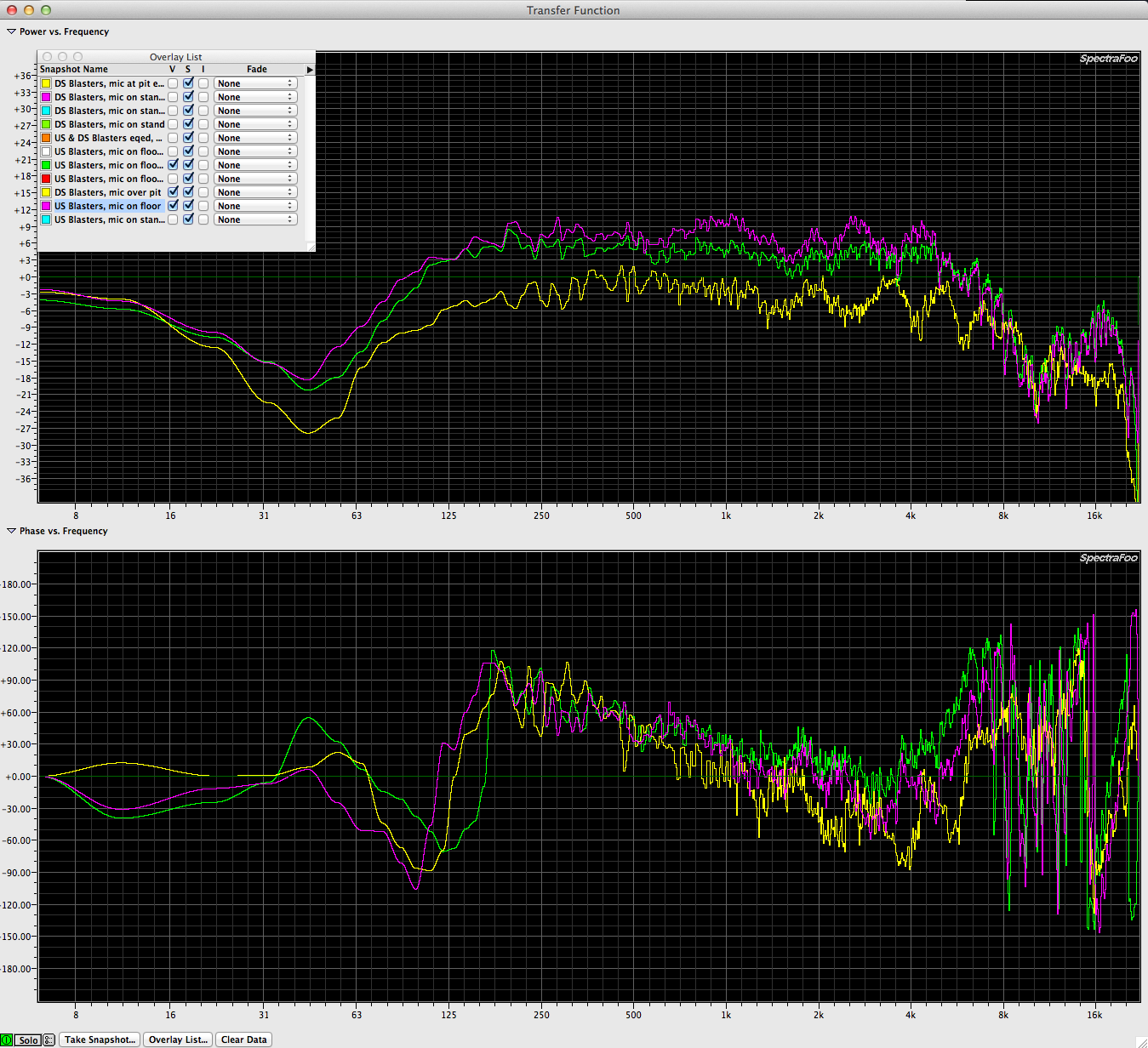
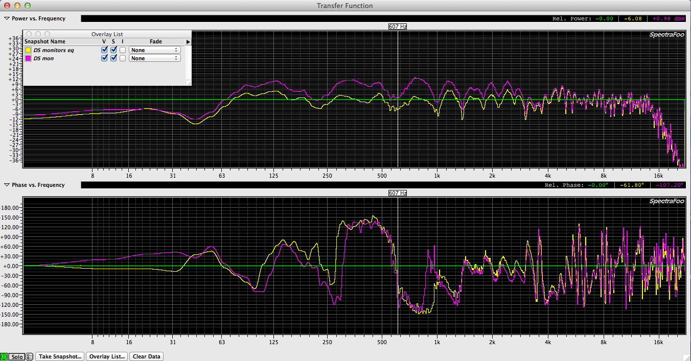
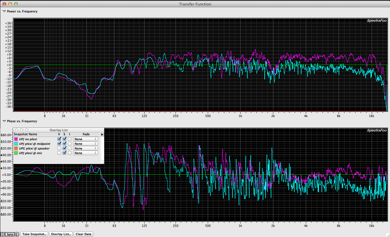
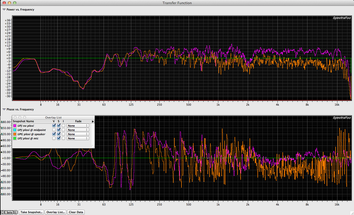
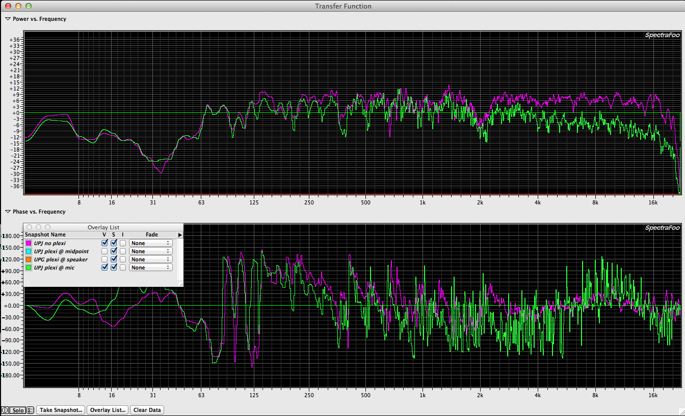
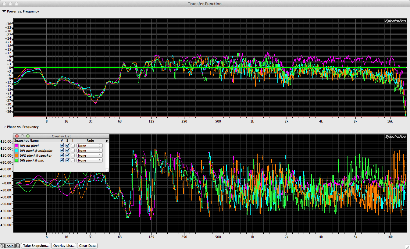
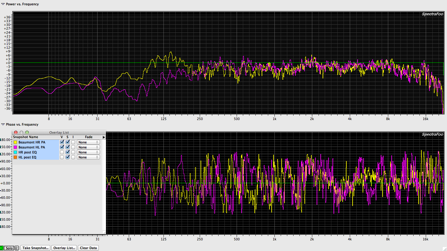
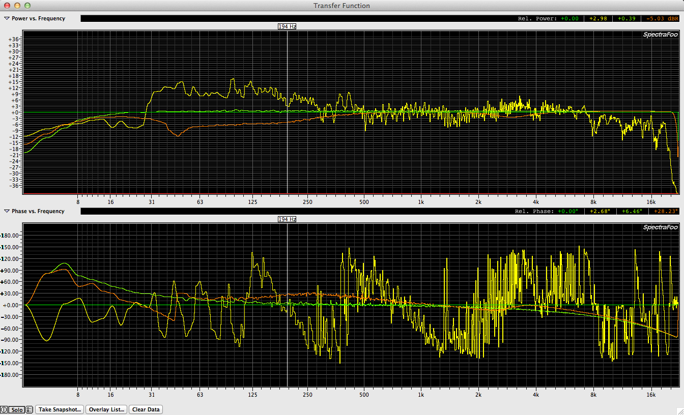
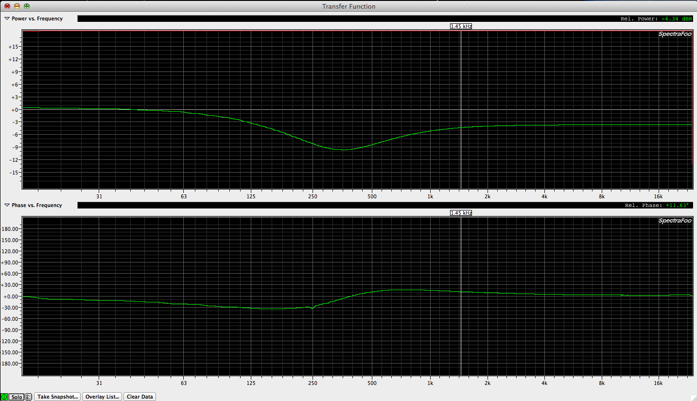
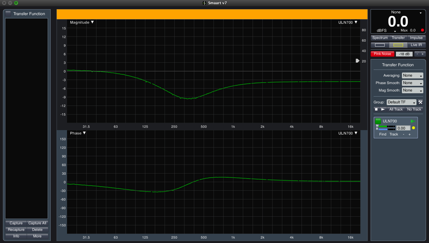
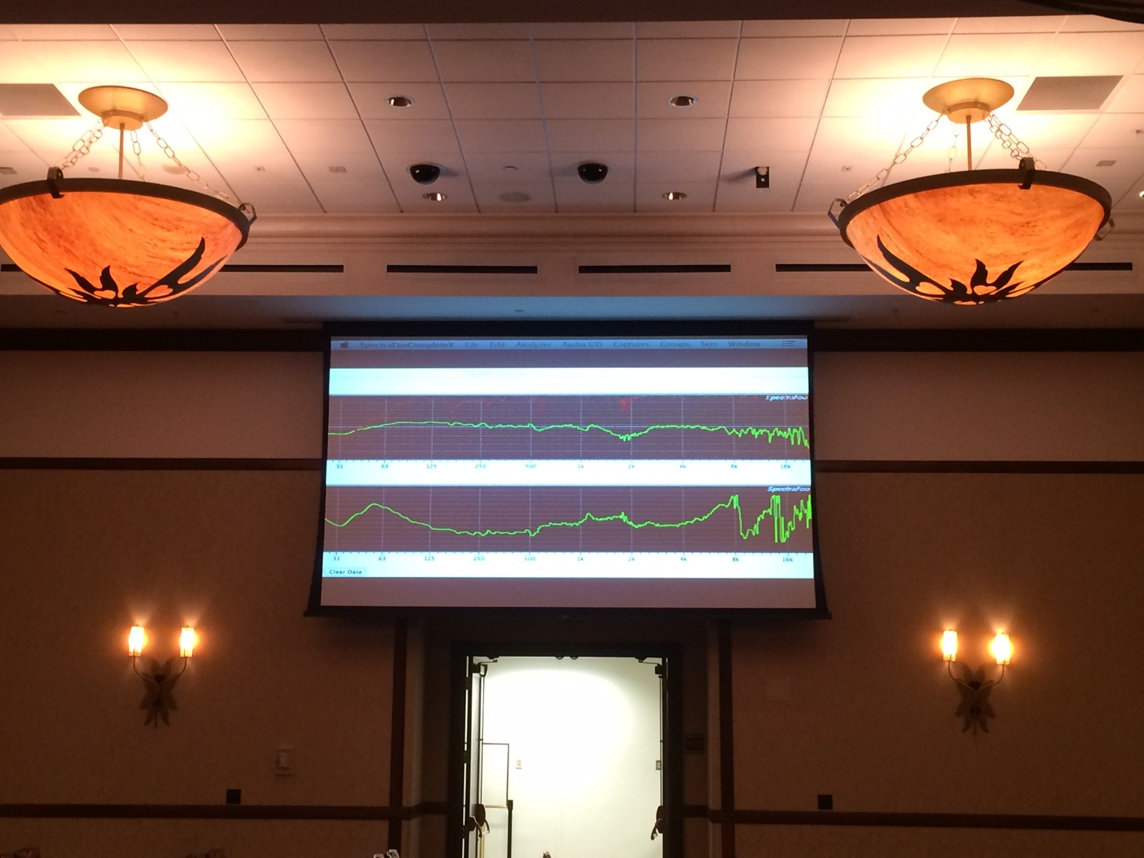
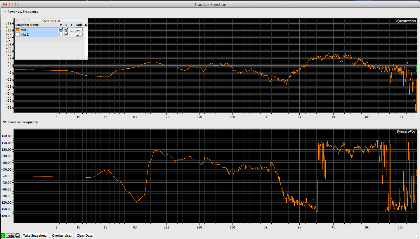
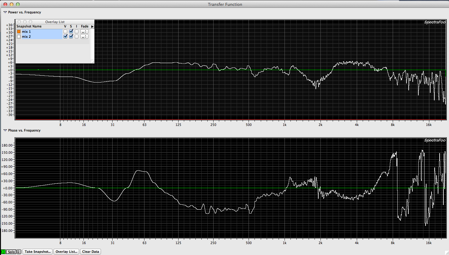
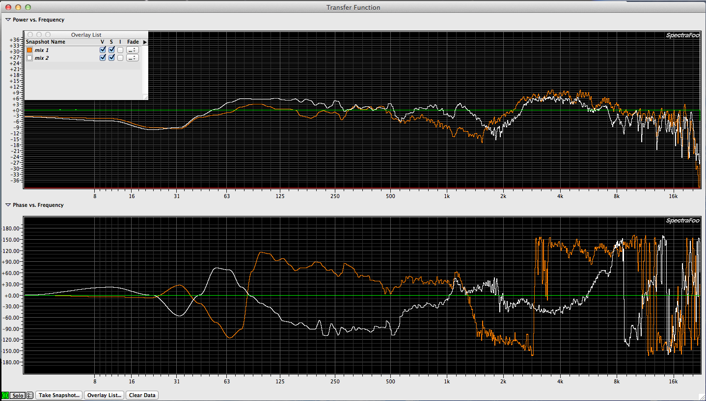
What would happen if we used an SM57 (the flatter of the two Shure mics) to tune a sound system?
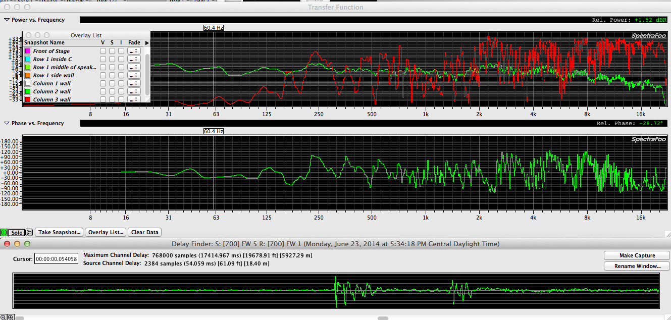
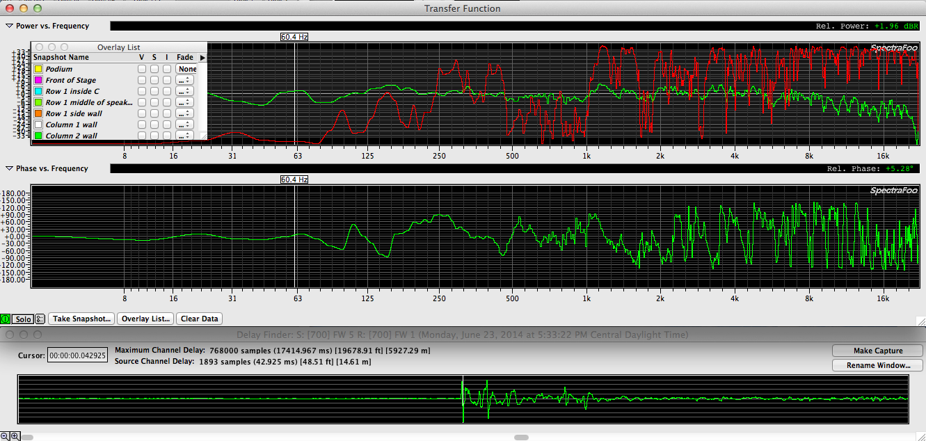
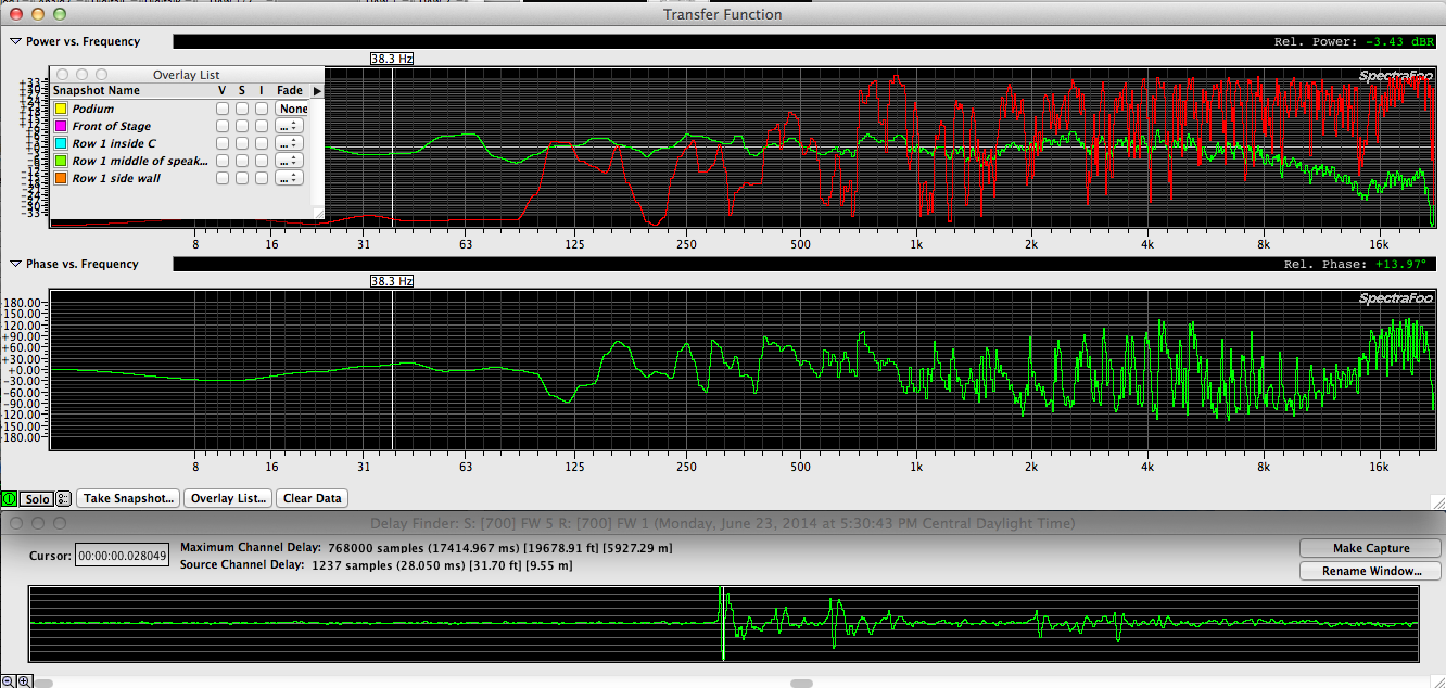
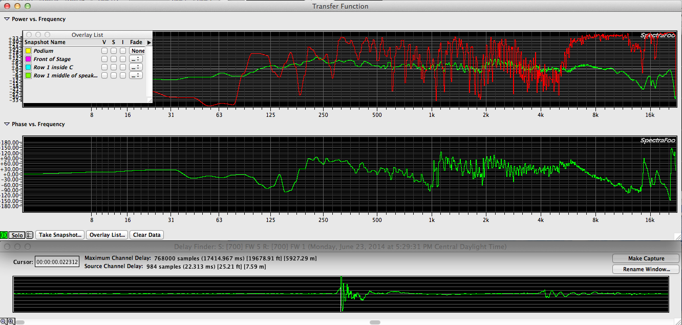
INSERT SIDE BY SIDE TRACES
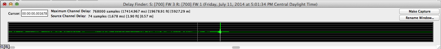 44.1k – 1.678 ms
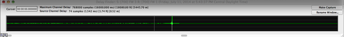 48k – 1.542 ms
 88k – .839 ms
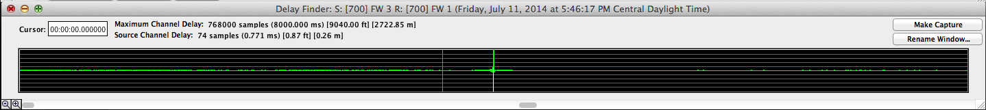 96k – .771 ms


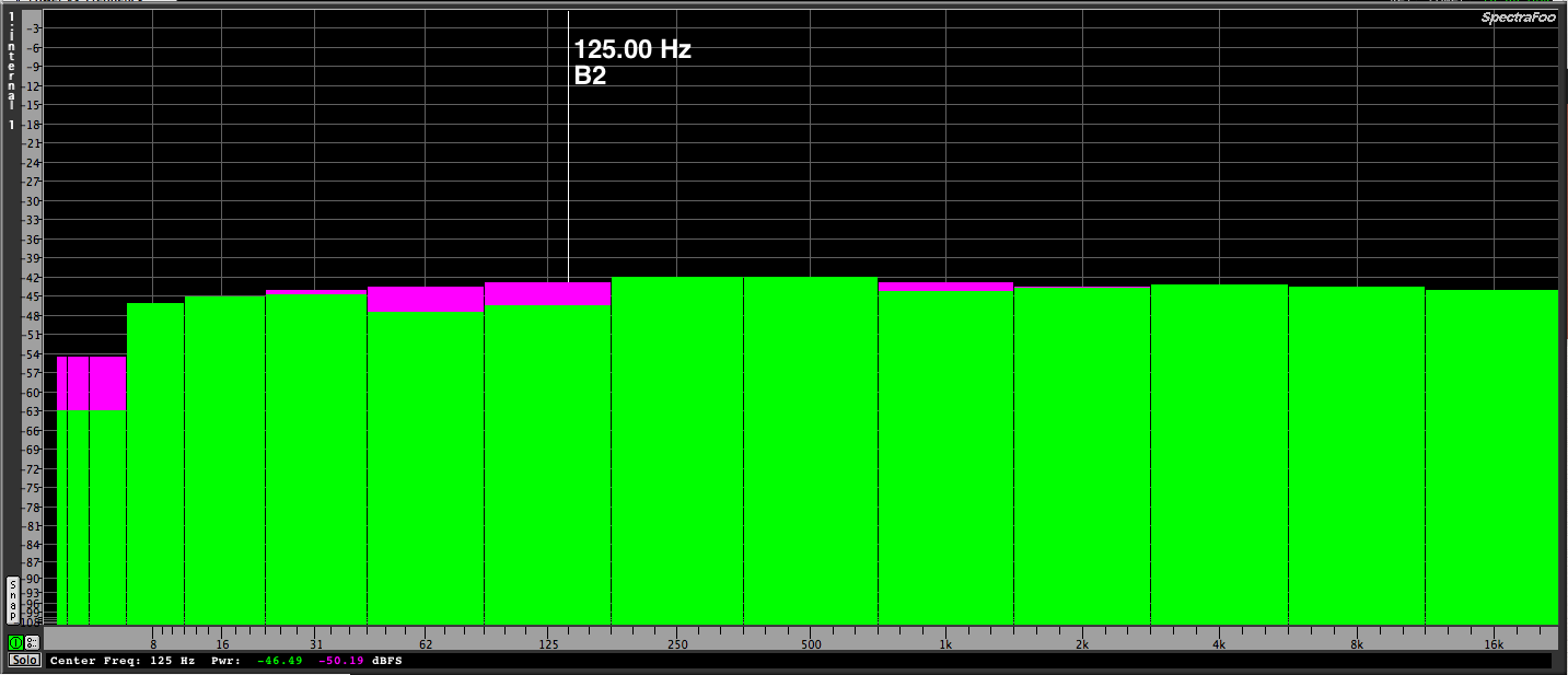 1 octave scale
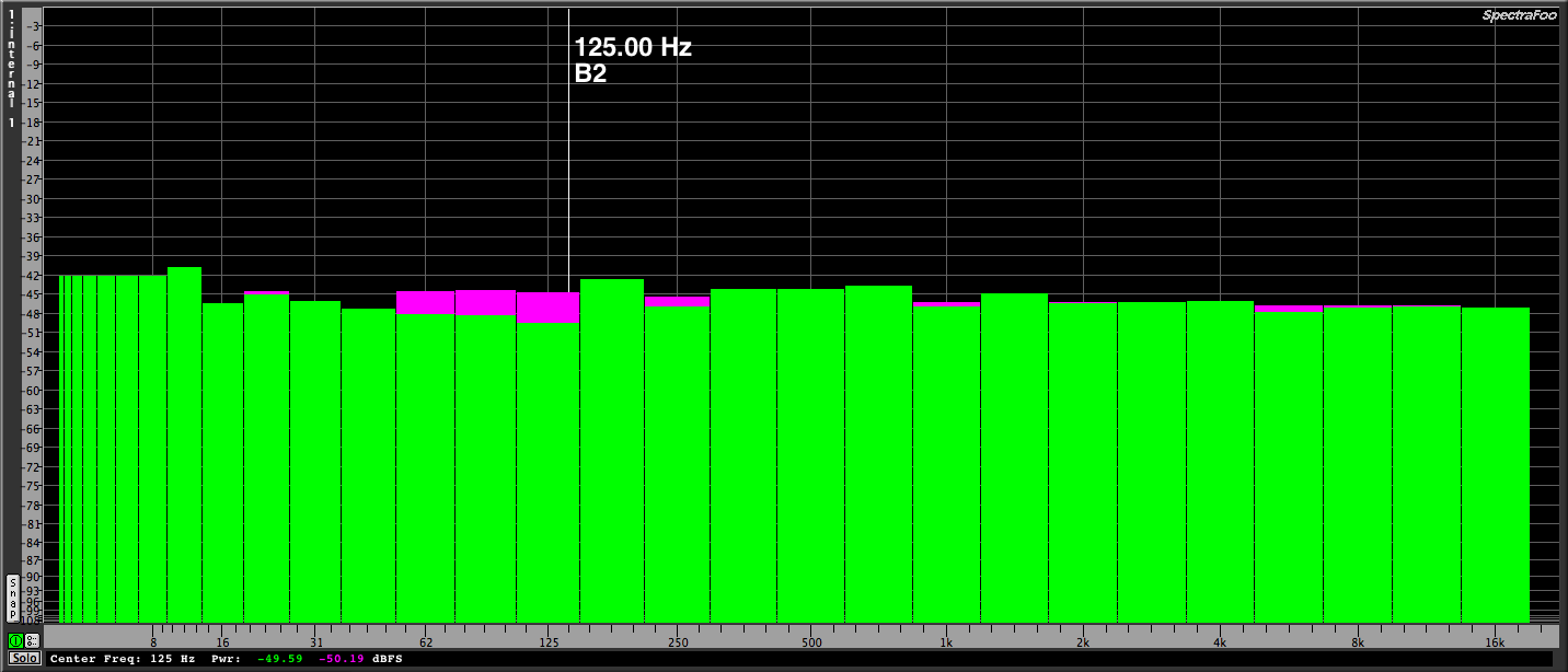 1/2 octave scale
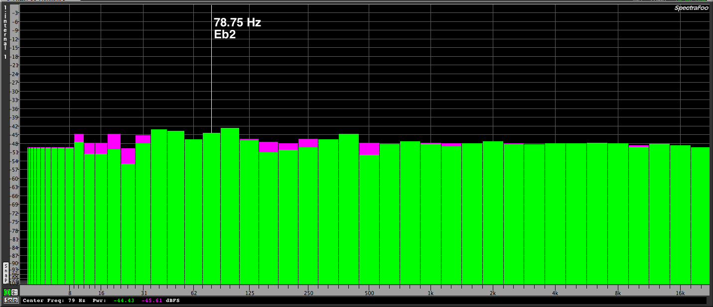 1/3 octave scale
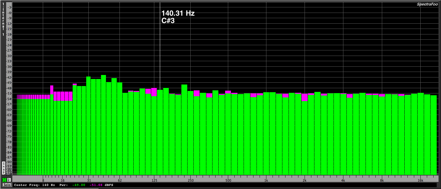 1/6 octave scale
 1/12 octave scale
 1/24 octave scale